NYISO Tariffs --> Open Access Transmission Tariff (OATT) --> 35 OATT Attachment CC - Joint Operating Agreement Among And --> 35.23 OATT Att CC Schedule D - M2M Coordination
35.23Schedule D – Market-to-Market Coordination Process – Version 1.0
NYISO & PJM
Market-to-Market Coordination Schedule
Table of Contents
1Overview of the Market-to-Market Coordination Process
2M2M Flowgates
3M2M Flowgate Studies
4Removal of M2M Flowgates
5Market Flow Determination
5.1Determine Shift Factors for M2M Flowgates
5.2Compute RTO Load Served by RTO Generation
5.3Compute RTO Generation Serving RTO Load
5.4Compute the RTO GTL for all M2M Flowgates
5.5Compute the RTO Interchange Scheduling Impacts for all M2M Flowgates
5.6Compute the PAR Effects for all M2M Flowgates
5.7Compute the RTO Aggregate Market Flow for all M2M Flowgates
6M2M Entitlement Determination Method
6.1M2M Entitlement Topology Model and Impact Calculation
6.2M2M Entitlement Calculation
6.3M2M Entitlement Adjustment for New Transmission Facilities or Upgraded Transmission Facilities
6.4M2M Entitlement Adjustment for a New Set of Generation, Load and Interchange Data
7Real-Time Energy Market Coordination
7.1Real-Time Redispatch Coordination Procedures
7.2Real-Time Ramapo PAR Coordination
8Real-Time Energy Market Settlements
8.1Information Used to Calculate M2M Settlements
8.2Real-Time Redispatch Settlement
8.3Ramapo PARs Settlement
8.4Calculating a Combined M2M Settlement
9When One of the RTOs Does Not Have Sufficient Redispatch
10Appropriate Use of the M2M Coordination Process
10.1Qualifying Conditions for M2M Settlement
10.2After-the-Fact Review to Determine M2M Settlement
10.3 Access to Data to Verify Market Flow Calculations
11M2M Change Management Process
11.1Notice
11.2Opportunity to Request Additional Information
11.3Objection to Change
11.4Implementation of Change
1Overview of the Market-to-Market Coordination Process
The purpose of the M2M coordination process is to set forth the rules that apply to M2M coordination between PJM and NYISO and the associated settlements processes.
The fundamental philosophy of the PJM/NYISO M2M coordination process is to set up procedures to allow any transmission constraints that are significantly impacted by generation dispatch changes and/or Phase Angle Regulator (“PAR”) control actions in both markets to be jointly managed in the security-constrained economic dispatch models of both RTOs. This joint management of transmission constraints near the market borders will provide the more efficient and lower cost transmission congestion management solution, while providing coordinated pricing at the market boundaries.
The M2M coordination process focuses on real-time market coordination to manage transmission limitations that occur on the M2M Flowgates in a more cost effective manner. Coordination between NYISO and PJM will include not only joint redispatch, but will also incorporate coordinated operation of the Ramapo PARs that are located at the NYISO – PJM interface. This real-time coordination will result in a more efficient economic dispatch solution across both markets to manage the real-time transmission constraints that impact both markets, focusing on the actual flows in real-time to manage constraints. Under this approach, the flow entitlements on the M2M Flowgates do not impact the physical dispatch; the flow entitlements are used in market settlements to ensure appropriate compensation based on comparison of the actual Market Flows to the flow entitlements.
2M2M Flowgates
Only a subset of all transmission constraints that exist in either market will require coordinated congestion management. This subset of transmission constraints will be identified as M2M Flowgates. Flowgates eligible for the M2M coordination process are called M2M Flowgates. For the purposes of the M2M coordination process (in addition to the studies described in section 3 below) the following will be used in determining M2M Flowgates.
2.1NYISO and PJM will only be performing the M2M coordination process on M2M Flowgates that are under the operational control of NYISO or PJM. NYISO and PJM will not be performing the M2M coordination process on Flowgates that are owned and controlled by third party entities.
2.2The Parties will make reasonable efforts to lower their generator binding threshold to match the lower generator binding threshold utilized by the other Party. The generator and Ramapo PAR binding thresholds (the shift factor thresholds used to identify the resource(s) available to relieve a transmission constraint), will not be set below 3%, except by mutual consent. This requirement applies to M2M Flowgates. It is not an additional criterion for determination of M2M Flowgates.
2.3For the purpose of determining whether a monitored element Flowgate is eligible for the M2M coordination process, a threshold for determining a significant GLDF or Ramapo PSF will take into account the number of monitored elements. Implementation of M2M Flowgates will ordinarily occur through mutual agreement.
2.4All Flowgates eligible for M2M coordination will be included in the coordinated
operations of the Ramapo PARs. Flowgates with significant GLDF will also be included in joint redispatch.
2.5M2M Flowgates that are eligible for redispatch coordination are also eligible for coordinated operation of the Ramapo PARs. M2M Flowgates that are eligible for coordinated operation of the Ramapo PARs are not necessarily also eligible for redispatch coordination.
2.6The NYISO shall post a list of all of the M2M Flowgates located in the NYCA on its web site. PJM shall post a list of all of the M2M Flowgates located in its Control Area on its web site.
3M2M Flowgate Studies
To identify M2M Flowgates the Parties will perform an off-line study to determine if the significant GLDF for at least one generator within the Non-Monitoring RTO, or significant PSF for at least one Ramapo PAR, on a potential M2M Flowgate within the Monitoring RTO is greater than or equal to the thresholds as described below. The study shall be based on an up-to-date power flow model representation of the Eastern Interconnection, with all normally closed Transmission Facilities in-service. The transmission modeling assumptions used in the M2M Flowgate studies will be based on the same assumptions used for determining M2M Entitlements in Section 6 below.
3.1Either Party may propose that a new M2M Flowgate be added at any time. The Parties will work together to perform the necessary studies within a reasonable timeframe.
3.2The GLDF or Ramapo PSF thresholds for M2M Flowgates with one or more monitored elements are defined as:
- Single monitored element, 5% GLDF/Ramapo PSF;
- Two monitored elements, 7.5% GLDF/Ramapo PSF; and
- Three or more monitored elements, 10% GLDF/Ramapo PSF.
3.3For potential M2M Flowgates that pass the above Ramapo PSF criteria, the Parties must still mutually agree to add each Flowgate as an M2M Flowgate for coordinated operation of the Ramapo PARs.
3.4For potential M2M Flowgates that pass the above GLDF criteria, the Parties must still mutually agree to add each Flowgate as an M2M Flowgate for redispatch coordination.
3.5The Parties can also mutually agree to add a M2M Flowgate that does not satisfy the above criteria.
4Removal of M2M Flowgates
Removal of M2M Flowgates from the systems may be necessary under certain conditions including the following:
4.1A M2M Flowgate is no longer valid when (a) a change is implemented that effects either Party’s generation impacts causing the Flowgate to no longer pass the M2M Flowgate Studies, or (b) a change is implemented that affects the impacts from coordinated operation of the Ramapo PARs causing the Flowgate to no longer pass the M2M Flowgate Studies. The Parties must still mutually agree to remove a M2M Flowgate, such agreement not to be unreasonably withheld. Once a M2M Flowgate has been removed, it will no longer be eligible for M2M settlement.
4.2A M2M Flowgate that does not satisfy the criteria set forth in Section 3.2 above, but that is created based on the mutual agreement of the Parties pursuant to Section 3.5 above, shall be removed two weeks after either Party provides a formal notice to the other Party that it withdraws its agreement to the M2M Flowgate, or at a later or earlier date that the Parties mutually agree upon. The formal notice must include an explanation of the reason(s) why the agreement to the M2M Flowgate was withdrawn.
4.3The Parties can mutually agree to remove a M2M Flowgate from the M2M coordination process whether or not it passes the coordination tests. A M2M Flowgate should be removed when the Parties agree that the M2M coordination process is not, or will not be, an effective mechanism to manage congestion on that Flowgate.
5Market Flow Determination
Each RTO will independently calculate its Market Flow for all M2M Flowgates using the equations set forth in this section. The Market Flow calculation is broken down into the following steps:
- Determine Shift Factors for M2M Flowgates
- Compute RTO Load and Losses (less imports)
- Compute RTO Generation (less exports)
- Compute RTO Generation to Load impacts on the Market Flow
- Compute RTO interchange scheduling impacts on the Market Flow
- Compute PAR impacts on the Market Flow
- Compute Market Flow
5.1Determine Shift Factors for M2M Flowgates
The first step to determining the Market Flow on a M2M Flowgate is to calculate generator, load and PAR shift factors for the each of the M2M Flowgates. For real-time M2M coordination, the shift factors will be based on the real-time transmission system topology.
5.2Compute RTO Load Served by RTO Generation
Using area load and losses for each load zone, compute the RTO Load, in MWs, by summing the load and losses for each load zone to determine the total zonal load for each RTO load zone. Twenty percent of RECo load shall be included in the Market Flow calculation as PJM load. See Section 6.2, below.
![]() , for each RTO load zone
, for each RTO load zone
Where:
zone =the relevant RTO load zone;
Zonal_Total_Loadzone =the sum of the RTO’s load and transmission losses for the zone;
Loadzone =the load within the zone; and
Losseszone =the transmission losses for transfers through the zone.
Next, reduce the Zonal Loads by the scheduled line real-time import transaction schedules that sink in that particular load zone:
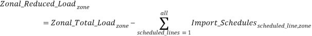
Where:
zone =the relevant RTO load zone;
scheduled_line =each of the Transmission Facilities identified in Table 1 below;
Zonal_Reduced_Loadzone =the sum of the RTO’s load and transmission losses in a zone reduced by the sum of import schedules over scheduled lines to the zone;
Zonal_Total_Loadzone =the sum of the RTO’s load and transmission losses for the zone; and
Import_Schedulesscheduled_line,zone =import schedules over a scheduled line to a zone.
The real-time import schedules over scheduled lines will only reduce the load in the sink load zones identified in Table 1 below:
Table 1. List of Scheduled Lines
Scheduled Line | NYISO Load Zone | PJM Load Zone |
Dennison Scheduled Line | North | Not Applicable |
Cross-Sound Scheduled Line | Long Island | Not Applicable |
HTP Scheduled Line | New York City | Mid-Atlantic Control Zone |
Linden VFT Scheduled Line | New York City | Mid-Atlantic Control Zone |
Neptune Scheduled Line | Long Island | Mid-Atlantic Control Zone |
Northport – Norwalk Scheduled Line | Long Island | Not Applicable |
Once import schedules over scheduled lines have been accounted for, it is then appropriate to reduce the net RTO Load by the remaining real-time import schedules at the proxies identified in Table 2 below:
Table 2. List of Proxies*
Proxy | Balancing Authorities Responsible |
PJM shall post and maintain a list of its proxies on its OASIS website. PJM shall provide to NYISO notice of any new or deleted proxies prior to implementing such changes in its M2M software. | PJM |
NYISO proxies are the Proxy Generator Buses that are not identified as Scheduled Lines in the table that is set forth in Section 4.4.4 of the NYISO’s Market Services Tariff. The NYISO shall provide to PJM notice of any new of deleted proxies prior to implementing such changes in its M2M software. | NYISO |
*Scheduled lines and proxies are mutually exclusive. Transmission Facilities that are components of a scheduled line are not also components of a proxy (and vice-versa).
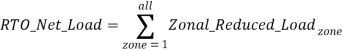
Where:
zone =the relevant RTO load zone;
RTO_Net_Load =the sum of load and transmission losses for the entire RTO footprint reduced by the sum of import schedules over all scheduled lines; and
Zonal_Reduced_Loadzone =the sum of the RTO’s load and transmission losses in a zone reduced by the sum of import schedules over scheduled lines to the zone.
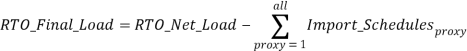
Where:
proxy =representations of defined sets of Transmission Facilities that (i) interconnect neighboring Balancing Authorities, (ii) are collectively scheduled, and (iii) are identified in Table 2 above;
RTO_Final_Load =the sum of the RTO’s load and transmission losses for the entire RTO footprint, sequentially reduced by (i) the sum of import schedules over all scheduled lines, and (ii) the sum of all proxy import schedules;
RTO_Net_Load =the sum of load and transmission losses for the entire RTO footprint reduced by the sum of import schedules over all scheduled lines; and
Import_Schedulesproxy =the sum of import schedules at a given proxy.
Next, calculate the Zonal Load weighting factor for each RTO load zone:
![]()
Where:
zone =the relevant RTO load zone;
Zonal_Weightingzone =the percentage of the RTO’s load contained within the zone;
RTO_Net_Load =the sum of load and transmission losses for the entire RTO footprint reduced by the sum of import schedules over all scheduled lines; and
Zonal_Reduced_Loadzone =the sum of the RTO’s load and transmission losses in a zone reduced by the sum of import schedules over scheduled lines to the zone.
Using the Zonal Weighting Factor compute the zonal load reduced by RTO imports for each load zone:
![]()
Where:
zone =the relevant RTO load zone;
Zonal_Final_Loadzone =the final RTO load served by internal RTO generation in the zone;
Zonal_Weightingzone =the percentage of the RTO’s load contained within the zone; and
RTO_Final_Load =the sum of the RTO’s load and transmission losses for the entire RTO footprint, sequentially reduced by (i) the sum of import schedules over all scheduled lines, and (ii) the sum of all proxy import schedules.
Using the Load Shift Factors (“LSFs”) calculated above, compute the weighted RTOLSF for each M2M Flowgate as:

Where:
M2M_Flowgate-m =the relevant flowgate;
zone =the relevant RTO load zone;
RTO_LSFM2M_Flowgate-m =the load shift factor for the entire RTO footprint on M2M Flowgate m;
LSF(zone,M2M_Flowgate-m) =the load shift factor for the RTO zone on M2M Flowgate m;
Zonal_Final_Loadzone =the final RTO load served by internal RTO generation in the zone; and
RTO_Final_Load =the sum of the RTO’s load and transmission losses for the entire RTO footprint, sequentially reduced by (i) the sum of import schedules over all scheduled lines, and (ii) the sum of all proxy import schedules.
5.3Compute RTO Generation Serving RTO Load
Using the real-time generation output in MWs, compute the Generation serving RTO Load. Sum the output of RTO generation within each load zone:
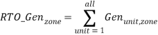 , for each RTO load zone
Where:
zone =the relevant RTO load zone;
unit =the relevant generator;
RTO_Genzone =the sum of the RTO’s generation in a zone; and
Genunit,zone =the real-time output of the unit in a given zone.
Next, reduce the RTO generation located within a load zone by the scheduled line real-time export transaction schedules that source from that particular load zone:

Where:
zone =the relevant RTO load zone;
scheduled_line =each of the Transmission Facilities identified in Table 1 above;
RTO_Reduced_Genzone =the sum of the RTO’s generation in a zone reduced by the sum of export schedules over scheduled lines from the zone;
RTO_Genzone =the sum of the RTO’s generation in a zone; and
Export_Schedulesscheduled_line,zone =export schedules from a zone over a scheduled line.
The real-time export schedules over scheduled lines will only reduce the generation in the source zones identified in Table 1 above. The resulting generator output based on this reduction is defined below.
![]()
Where:
unit =the relevant generator;
zone =the relevant RTO load zone;
Genunit,zone =the real-time output of the unit in a given zone;
Reduced Genunit =each unit’s real-time output after reducing the RTO_Net_Gen by the real-time export schedules over scheduled lines;
RTO_Reduced_Genzone =the sum of the RTO’s generation in a zone reduced by the sum of export schedules over scheduled lines from the zone; and
RTO_Genzone =the sum of the RTO’s generation in a zone.
Once export schedules over scheduled lines are accounted for, it is then appropriate to reduce the net RTO generation by the remaining real-time export schedules at the proxies identified in Table 2 above.
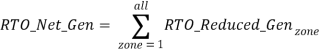
Where:
zone =the relevant RTO load zone;
RTO_Net_Gen =the sum of the RTO’s generation reduced by the sum of export schedules over all scheduled lines; and
RTO_Reduced_Genzone =the sum of the RTO’s generation in a zone reduced by the sum of export schedules over scheduled lines from the zone.
Where:
proxy =representation of defined sets of Transmission Facilities that (i) interconnect neighboring Balancing Authorities, (ii) are collectively scheduled, and (iii) are identified in Table 2 above;
RTO_Final_Gen =the sum of the RTO’s generation output for the entire RTO footprint, sequentially reduced by (i) the sum of export schedules over all scheduled lines, and (ii) the sum of all proxy export schedules;
RTO_Net_Gen =the sum of the RTO’s generation reduced by the sum of export schedules over all scheduled lines; and
Export_Schedulesproxy =the sum of export schedules at a given proxy.
Finally, weight each generator’s output by the reduced RTO generation:
![]()
Where:
unit =the relevant generator;
Gen_Finalunit =the portion of each unit’s output that is serving the RTO Net Load;
Reduced Genunit =each unit’s real-time output after reducing the RTO_Net_Gen by the real-time export schedules over scheduled lines;
RTO_Final_Gen =the sum of the RTO’s generation output for the entire RTO footprint, sequentially reduced by (i) the sum of export schedules over all scheduled lines, and (ii) the sum of all proxy export schedules; and
RTO_Net_Gen =the sum of the RTO’s generation reduced by the sum of export schedules over all scheduled lines.
5.4Compute the RTO GTL for all M2M Flowgates
The generation-to-load flow for a particular M2M Flowgate, in MWs, will be determined as:

Where:
M2M_Flowgate-m =the relevant flowgate;
unit =the relevant generator;
RTO_GTLM2M_Flowgate-m =the generation to load flow for the entire RTO footprint on M2M Flowgate m;
Gen_Finalunit =the portion of each unit’s output that is serving RTO Net Load;
GSF(unit,M2M_Flowgate-m) =the generator shift factor for each unit on M2M Flowgate m; and
RTO_LSFM2M_Flowgate-m =the load shift factor for the entire RTO footprint on M2M Flowgate m.
5.5Compute the RTO Interchange Scheduling Impacts for all M2M Flowgates
For each scheduling point that the participating RTO is responsible for, determine the net interchange schedule in MWs. Table 3 below identifies both the participating RTO that is responsible for each listed scheduling point, and the “type” assigned to each listed scheduling point.
Table 3. List of Scheduling Points
Scheduling Point | Scheduling Point Type | Participating RTO(s) Responsible |
NYISO-PJM | common | NYISO and PJM |
HTP Scheduled Line | common | NYISO and PJM |
Linden VFT Scheduled Line | common | NYISO and PJM |
Neptune Scheduled Line | common | NYISO and PJM |
PJM shall post and maintain a list of its non-common scheduling points on its OASIS website. PJM shall provide to NYISO notice of any new or deleted non-common scheduling points prior to implementing such changes in its M2M software. | non-common | PJM |
NYISO non-common scheduling points include all Proxy Generator Buses and Scheduled Lines listed in the table that is set forth in Section 4.4.4 of the NYISO’s Market Services Tariff that are not identified in this Table 3 as common scheduling points. The NYISO shall provide to PJM notice of any new or deleted non-common scheduling points prior to implementing such changes in its M2M software. | non-common | NYISO |
![]()
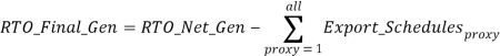
Where:
sched_pt =the relevant scheduling point. A scheduling point can be either a proxy or a scheduled line;
RTO_Transferssched_pt =the net interchange schedule at a scheduling point;
Importssched_pt =the import component of the interchange schedule at a scheduling point;
WheelsInsched_pt =the injection of wheels-through component of the interchange schedule at a scheduling point;
Exportssched_pt =the export component of the interchange schedule at a scheduling point; and
WheelsOutsched_pt =the withdrawal of wheels-through component of the interchange schedule at a scheduling point.
The equation below applies to all non-common scheduling points that only one of the participating RTOs is responsible for. Parallel_Transfers are applied to the Market Flow of the responsible participating RTO. For example, the Parallel_Transfers computed for the IESO-NYISO non-common scheduling point are applied to the NYISO Market Flow.
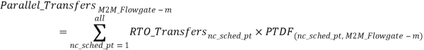
Where:
M2M_Flowgate-m =the relevant flowgate;
nc_sched_pt =the relevant non-common scheduling point. A non-common scheduling point can be either a proxy or a scheduled line. Non-common scheduling points are identified in Table 3, above;
Parallel_TransfersM2M_Flowgate-m =the flow on M2M Flowgate m due to the net interchange schedule at the non-common scheduling point;
RTO_Transfersnc_sched_pt =the net interchange schedule at the non-common scheduling point, where a positive number indicates the import direction; and
PTDF(nc_sched_pt, M2M_Flowgate-m) =the power transfer distribution factor of the non-common scheduling point on M2M Flowgate m. For NYISO, the PTDF will equal the generator shift factor of the non-common scheduling point.
The equation below applies to common scheduling points that directly interconnect the participating RTOs. Shared_Transfers are applied to the Monitoring RTO’s Market Flow only. NYISO to PJM transfers would be considered part of NYISO’s Market Flow for NYISO-monitored Flowgates and part of PJM’s Market Flow for PJM-monitored Flowgates.
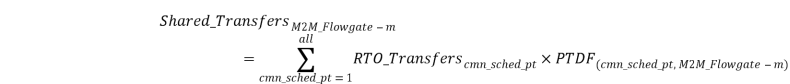
Where:
M2M_Flowgate-m =the relevant flowgate;
cmn_sched_pt =the relevant common scheduling point. A common scheduling point can be either a proxy or a scheduled line. Common scheduling points are identified in Table 3, above;
Shared_TransfersM2M_Flowgate-m =the flow on M2M Flowgate m due to interchange schedules on the common scheduling point;
RTO_Transferscmn_sched_pt =the net interchange schedule at a common scheduling point, where a positive number indicates the import direction; and
PTDF(cmn_sched_pt, M2M_Flowgate-m) =the generation shift factor of the common scheduling point on M2M Flowgate m. For NYISO, the PTDF will equal the generator shift factor of the common scheduling point.
5.6Compute the PAR Effects for all M2M Flowgates
For the PARs listed in Table 4 below, the RTOs will determine the generation-to-load flows and interchange schedules, in MWs, that each PAR is impacting.
Table 4. List of Phase Angle Regulators
PAR | Description | PAR Type | Actual Schedule | Target Schedule | Responsible Participating RTO(s) |
1 | RAMAPO PAR3500 | common | From telemetry | From telemetry* | NYISO and PJM |
2 | RAMAPO PAR4500 | common | From telemetry | From telemetry* | NYISO and PJM |
3 | FARRAGUT TR11 | common | From telemetry | From telemetry† | NYISO and PJM |
4 | FARRAGUT TR12 | common | From telemetry | From telemetry† | NYISO and PJM |
5 | GOETHSLN BK_1N | common | From telemetry | From telemetry† | NYISO and PJM |
6 | WALDWICK O2267 | common | From telemetry | From telemetry† | NYISO and PJM |
7 | WALDWICK F2258 | common | From telemetry | From telemetry† | NYISO and PJM |
8 | WALDWICK E2257 | common | From telemetry | From telemetry† | NYISO and PJM |
9 | STLAWRNC PS_33 | non-common | From telemetry | 0 | NYISO |
10 | STLAWRNC PS_34 | non-common | From telemetry | 0 | NYISO |
*Pursuant to the rules for implementing the M2M coordination process over the Ramapo PARs that are set forth in this M2M Schedule.
†Consistent with Schedule C to the Joint Operating Agreement between the Parties.
Compute the PAR control as the actual flow less the target flow across each PAR:
![]()
Where:
par =each of the phase angle regulators listed in Table 4, above;
PAR_Controlpar =the flow deviation on each of the PARs;
Actual_MWpar =the actual flow on each of the PARs, determined consistent with Table 4 above; and
Target_MWpar =the target flow that each of the PARs should be achieving, determined in accordance with Table 4 above.
When the Actual_MW and Target_MW are both set to “From telemetry” in Table 4 above, the PAR_Control will equal zero.
Common PARs
In the equations below, the Non-Monitoring RTO is credited for or responsible for PAR_Impact resulting from the common PAR effect on the Monitoring RTO’s M2M Flowgates. The common PAR impact calculation only applies to the common PARs identified in Table 4 above.
Compute control deviation for all common PARs on M2M Flowgate m based on the PAR_Controlpar MWs calculated above:
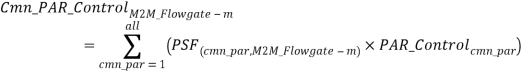
Where:
M2M_Flowgate-m =the relevant flowgate;
cmn_par =each of the common phase angle regulators, modeled as Flowgates, identified in Table 4, above;
Cmn_PAR_ControlM2M_Flowgate-m =the sum of flow on M2M Flowgate m after accounting for the operation of common PARs;
PSF(cmn_par,M2M_Flowgate-m) =the PSF of each of the common PARs on M2M Flowgate m; and
PAR_Controlcmn_par =the flow deviation on each of the common PARs.
Compute the impact of generation-to-load and interchange schedules across all common PARs on M2M Flowgate m as the Market Flow across each common PAR multiplied by that PAR’s shift factor on M2M Flowgate m:
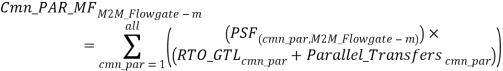
Where:
M2M_Flowgate-m =the relevant flowgate;
cmn_par =the set of common phase angle regulators, modeled as Flowgates, identified in Table 4 above;
Cmn_PAR_MFM2M_Flowgate-m =the sum of flow on M2M Flowgate m due to the generation to load flows and interchange schedules on the common PARs;
PSF(cmn_par,M2M_Flowgate-m) =the PSF of each of the common PARs on M2M Flowgate m;
RTO_GTLcmn_par =the generation to load flow for each common par, computed in the same manner as the generation to load flow is computed for M2M Flowgates in Section 5.4 above; and
Parallel_Transferscmn_par =the flow on each of the common PARs caused by interchange schedules at non-common scheduling points.
Next, compute the impact of the common PAR effect for M2M Flowgate m as:
![]()
Where:
M2M_Flowgate-m =the relevant flowgate;
Cmn_PAR_ImpactM2M_Flowgate-m =potential flow on M2M Flowgate m that is affected by the operation of the common PARs;
Cmn_PAR_MFM2M_Flowgate-m =the sum of flow on M2M Flowgate m due to the generation to load and interchange schedules on the common PARs; and
Cmn_PAR_ControlM2M_Flowgate-m =the flow deviation on each of the common PARs.
Non-Common PARs
For the equations below, the NYISO will be credited or responsible for PAR_Impact on all M2M Flowgates because the NYISO is the participating RTO that has input into the operation of these devices. The non-common PAR impact calculation only applies to the non-common PARs identified in Table 4 above.
Compute control deviation for all non-common PARs on M2M Flowgate m based on the PAR control MW above:

Where:
M2M_Flowgate-m =the relevant flowgate;
nc_par =each of the non-common phase angle regulators, modeled as Flowgates, identified in Table 4 above;
NC_PAR_ControlM2M_Flowgate-m =the sum of flow on M2M Flowgate m after accounting for the operation of non-common PARs;
PSF(nc_par,M2M_Flowgate-m) =the PSF of each of the non-common PARs on M2M Flowgate m; and
PAR_Controlnc_par =the flow deviation on each of the non-common PARs.
Compute the impact of generation-to-load and interchange schedules across all non-common PARs on M2M Flowgate m as the Market Flow across each PAR multiplied by that PAR’s shift factor on M2M Flowgate m:

Where:
M2M_Flowgate-m =the relevant flowgate;
nc_par =the set of non-common phase angle regulators, modeled as Flowgates, identified in Table 4 above;
NC_PAR_MFM2M_Flowgate-m =the sum of flow on M2M Flowgate m due to the generation to load flows and interchange schedules on the non-common PARs;
PSF(nc_par,M2M_Flowgate-m) =the outage transfer distribution factor of each of the non-common PARs on M2M Flowgate m;
RTO_GTLnc_par =the generation to load flow for each non-common par, computed in the same manner as the generation to load flow is computed for M2M Flowgates in Section 5.4 above; and
Parallel_Transfersnc_par =the flow, as computed above where the M2M Flowgate m is one of the non-common PARs, on each of the non-common PARs caused by interchange schedules at non-common scheduling points.
Next, compute the non-common PAR impact for M2M Flowgate m as:
![]()
Where:
M2M_Flowgate-m =the relevant flowgate;
NC_PAR_ImpactM2M_Flowgate-m =the potential flow on M2M Flowgate m that is affected by the operation of non-common PARs;
NC_PAR_MFM2M_Flowgate-m =the sum of flow on M2M Flowgate m due to the generation to load and interchange schedules on the non-common PARs; and
NC_PAR_ControlM2M_Flowgate-m =the sum of flow on M2M Flowgate m after accounting for the operation of non-common PARs.
Aggregate all PAR Effects for Each M2M Flowgate
The total impacts from the PAR effects for M2M Flowgate m is:
![]()
Where:
M2M_Flowgate-m =the relevant flowgate;
PAR_ImpactM2M_Flowgate-m =the flow on M2M Flowgate m that is affected after accounting for the operation of both common and non-common PARs;
Cmn_PAR_ImpactM2M_Flowgate-m =potential flow on M2M Flowgate m that is affected by the operation of the common PARs; and
NC_PAR_ImpactM2M_Flowgate-m =the potential flow on M2M Flowgate m that is affected by the operation of non-common PARs.
5.7Compute the RTO Aggregate Market Flow for all M2M Flowgates
With the RTO_GTL and PAR_IMPACT known, we can now compute the RTO_MF for all M2M Flowgates as:
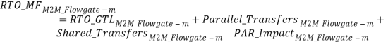
Where:
M2M_Flowgate-m =the relevant flowgate;
RTO_MFM2M_Flowgate-m = the Market Flow caused by RTO generation dispatch and
transaction scheduling on M2M Flowgate m after accounting for the operation of both the common and non-common PARs;
RTO_GTLM2M_Flowgate-m =the generation to load flow for the entire RTO footprint on M2M Flowgate m;
Parallel_TransfersM2M_Flowgate-m =the flow on M2M Flowgate m caused by interchange schedules that are not jointly scheduled by the participating RTOs;
Shared_TransfersM2M_Flowgate-m =the flow on M2M Flowgate m caused by interchange schedules that are jointly scheduled by the participating RTOs; and
PAR_ImpactM2M_Flowgate-m =the flow on M2M Flowgate m that is affected after accounting for the operation of both the common and non-common PARs.
6M2M Entitlement Determination Method
M2M Entitlements are the equivalent of financial rights for the Non-Monitoring RTO to use the Monitoring RTO’s transmission system within the confines of the M2M redispatch process. The Parties worked together to develop the M2M Entitlement determination method set forth below.
Each Party shall calculate a M2M Entitlement on each M2M Flowgate and compare the results on a mutually agreed upon schedule.
6.1M2M Entitlement Topology Model and Impact Calculation
The M2M Entitlement calculation shall be based on ause both RTOs’ static topological modelmodels to determine a nonthe Non-Monitoring RTO’s mutually agreed upon share of a M2M Flowgate’s total capacity based on historic dispatch patterns. The modelBoth RTOs’ models must include the following items:
- a static transmission and generation model;
- generator, load, and PAR shift factors;
- generator output, load, and interchange schedules from 2009 through 2011 or any subsequent three year period mutually agreed to by the Parties;
- a PAR impact assumption that the PAR control is perfect for all PARs within the transmission
modelmodels except the PARs at the Michigan-Ontario border;and - new or upgraded Transmission Facilities
.; and - Transmission Facility retirements.
The Parties Each Party shall calculate the GLDFs using a transmission model that contains a mutually agreed upon set of: (1) transmission lines that are modeled as in-service; (2) generators; and (3) loads. Using these GLDFs, generator output data from the three year period agreed to by the Parties, and load data from the three year period agreed to by the Parties, the Parties shall calculate each Party’s MW impact on each M2M Flowgate for each hour in the three year period agreed to by the Parties.
Using these impacts, the Parties shall create a reference year consisting of four periods (“M2M Entitlement Periods”) for each M2M Flowgate. The M2M Entitlement Periods are as follows:
- M2M Entitlement Period 1: December, January, and February;
- M2M Entitlement Period 2: March, April, and May;
- M2M Entitlement Period 3: June, July, and August; and
- M2M Entitlement Period 4: September, October, and November.
For each of the M2M Entitlement Periods listed above the Non-Monitoring RTO will calculate its M2M Entitlement on each M2M Flowgate for each hour of each day of a week that will serve as the representative week for that M2M Entitlement Period. The M2M Entitlement for each day/hour, for each M2M Flowgate will be calculated by averaging the Non-Monitoring RTO’s Market Flow on an M2M Flowgate for each particular day/hour of the week. The Non-Monitoring RTO shall use the Market Flow data for all of the like day/hours, that occurred in that day of the week and hour in the M2M Entitlement Period, in each year contained within the three year period agreed to by the Parties to calculate the Non-Monitoring RTO’s average Market Flow on each M2M Flowgate. When determining M2M settlements each Party will use the M2M Entitlement that corresponds to the hour of the week and to the M2M Entitlement Period for which the real-time Market Flow is being calculated.
The Parties will use the M2M Entitlements that are calculated based on data from the 2009 through 2011 three year period for at least their first year of implementing the M2M coordination process.
6.2M2M Entitlement Calculation
Each Party shall independently calculate the Non-Monitoring RTO’s M2M Entitlement for all M2M Flowgates using the equations set forth in this section. The Parties shall mutually agree upon M2M Entitlement calculations. Any disputes that arise in the M2M Entitlement calculations will be resolved in accordance with the dispute resolution procedures set forth in section 35.15 of the Agreement.
Eighty percent of the RECo load shall be excluded from the calculation of Market Flows and M2M Entitlements, and shall instead be reflected as a PJM obligation over the Ramapo PARs in accordance with Sections 7.2.1 and 8.3 of this M2M Schedule D. The remaining twenty percent of RECo load shall be included in the M2M Entitlement and Market Flow calculations as PJM load.
The following assumptions apply to the M2M Entitlement calculation:
- the Parties shall calculate the values in this section using the M2M Entitlement Topology Model discussed in Section 6.1 above, unless otherwise stated;
- the impacts from the Parallel_Transfers and Shared_Transfers terms of the Market Flow calculation (see Section 5.5) are excluded from the Market Flow that is used to calculate M2M Entitlements;
- perfect PAR Control exists for all PARs within the transmission
modelmodels except the PARs at the Ontario/Michigan border; and - External Capacity Resources may be included in the calculation of M2M Entitlements consistent with Section 6.2.1.1 below.
Once the Reference Year Market Flows have been calculated for each interval to determine the integrated hourly Market Flow for each hour of the relevant three year period agreed to by the Parties, the new M2M Entitlement will be determined for a representative week in each M2M Entitlement Period using the method established in Section 6.1 above. In the event of new or upgraded Transmission Facilities, Section 6.3 below sets forth the rules that will be used to adjust M2M Entitlements.
6.2.1Treatment of Out-of-Area Capacity Resources and Representation of Ontario/Michigan PARs in the M2M Entitlement Calculation Process
6.2.1.1Modeling of External Capacity Resources
External Capacity Resources may be included in the M2M Entitlement calculation to the extent the Parties mutually agree to their inclusion.
For the initial implementation of this M2M coordination process that will use 2009 through 2011 data to develop M2M Entitlements, PJM will be permitted to include its External Capacity Resources in the M2M Entitlement calculation. NYISO has not requested inclusion of any External Capacity Resources in the M2M Entitlement calculation for the initial implementation of M2M. When the Parties decide to update the data used to determine M2M Entitlements:
a.PJM will be permitted to include External Capacity Resources that have an equivalent net M2M Entitlement impact to the net M2M Entitlement impact of the PJM External Capacity Resources that were used for the initial implementation of the M2M coordination process. Inclusion of PJM External Capacity Resources that exceed the net M2M Entitlement impact of the PJM External Capacity Resources that were used for the initial implementation of the M2M coordination process must be mutually agreed to by the Parties.
b.The Parties may mutually agree to permit the NYISO to include External Capacity Resources in the M2M Entitlement calculation.
6.2.1.2Modeling of the Ontario/Michigan PARs
The Ontario/Michigan PARs will be modeled as not controlling power flows in the M2M Entitlement calculation process. The Parties agree that this modeling treatment is only appropriate when it is paired with the rules for calculating Market Flows and M2M settlements that are set forth in Sections 5 and 8 of this Agreement. Section 7.1 specifies how the RTOs will adjust Market Flows to account for the impact of the operation of the Ontario/Michigan PARs when the PARs are in service. The referenced Market Flow and M2M settlement rules are necessary because they are designed to ensure that M2M settlement obligations based on M2M Entitlements and Market Flows will not result in compensation for M2M redispatch when no actual M2M redispatch occurs.
6.3M2M Entitlement Adjustment for New Transmission Facilities or, Upgraded Transmission Facilities or Retired Transmission Facilities
This section sets forth the rules for incorporating new or upgraded Transmission Facilities, and Transmission Facility retirements, into the M2M Entitlement calculation. For all M2M Entitlement adjustments, the non-building RTO is the non-funding market, and the building RTO is the funding market.
If the cost of a new or upgraded Transmission Facility is borne solely by the Market Participants of the building RTO for the new or upgraded Transmission Facility, the Market Participants of the building RTO will exclusively benefit from the increase in transfer capability on the building RTO’s Transmission Facilities. Therefore, the non-building RTO’s M2M Entitlements shall not increase as result of such new or upgraded Transmission Facilities. Reciprocally, a building RTO’s M2M Entitlements on the non-building RTO’s M2M Flowgates shall not increase as a result of such new or upgraded Transmission Facilities.
To the extent a building RTO’s new or upgraded or new Transmission Facility, or Transmission Facility retirement, reduces the non-building RTO’s impacts on one or more of the building RTO’s M2M Flowgates by redistributing the non-building RTO’s modeled flows, the non-building RTO’s M2M Entitlement will be redistributed to ensure that the non-building RTO’s aggregate M2M Entitlements on the building RTOs transmission system, including both existing M2M Flowgates and upgraded or new Transmission Facilities that are not yet M2M Flowgates, is not decreased.
In assessing the impact of transmission upgrades or new or upgraded Transmission Facilities, or Transmission Facility retirements, the non-building RTO’s revised total circulation through the building RTO shall not result in a net increase in M2M Entitlements for the non-building RTO on the building RTO’s transmission system. The formulas below shall be used to determine the pro-rata adjustment that will be applied to determine the redistributed interval level and hourly integrated Market Flow (i.e., the Transmission Adjusted Market Flow). Once a Transmission Adjusted Market Flow that incorporates the topology adjustment and reallocation of flows has been calculated for each hour of the three year period agreed to by the Parties, the new M2M Entitlement will be determined for each hour and day of the week in each M2M Entitlement Period using the method established in Section 6.1 above.
The Parties will mutually perform an analysis to determine if new or upgraded Transmission Facilities, or Transmission Facility retirements, will have an impact on any of the non-building RTO’s M2M Flowgates. If the new or upgraded Transmission Facilities, or Transmission Facility retirements, are determined to have a 5% or less impact on each of the non-building RTO’s M2M Flowgates, calculated individually for each M2M Flowgate, then the non-building RTO is not required to update its operational models to incorporate the new, upgraded or retired Transmission Facilities. If the new or upgraded Transmission Facilities, or Transmission Facility retirements, are determined to have greater than a 5% impact, but less than a 10% impact on each of the non-building RTO’s M2M Flowgates, calculating the impact individually for each M2M Flowgate, then the Parties may mutually agree not to require the non-building RTO to update its operational models.
If Transmission Facilities outside the Balancing Authority Areas of the Parties are added or upgraded and the new or upgraded Transmission Facilities would, individually or in aggregate, cause a change in either Party’s aggregate M2M Entitlements of at least 10%, then the Parties may mutually agree to incorporate those Transmission Facilities into the static transmission modelmodels used to perform the M2M Entitlement calculations.
M2M Entitlement Transmission Adjusted Market Flow Calculation:
This process determines the Transmission Adjusted Market Flow for existing and new or retired Transmission Facilities when new Transmission Facilities are built or existing Transmission Facilities are upgraded or retired. This process does not apply to the addition of new M2M Flowgates that are associated with existing Transmission Facilities.
First, determine the reference set of Market Flows, called Reference Year Market Flows, for all M2M Flowgates using a static transmission model before adding any new or upgraded or newTransmission Facilities, or removing retired Transmission Facilities.
Second, account for new or upgraded Transmission Facilities or Transmission Facility retirements in order from the first completed new/upgraded/retired facility to the last (most recently completed) new/upgraded/retired facility. Reflect the new/upgraded/retired facilities, grouped by building RTO, in the reference year model to determine the new set of Market Flows called New Year Market Flows.
Third, compare the New Year Market Flows to the Reference Year Market Flows, in net across all M2M Flowgates and (after adding new or upgraded or new Transmission Facilities, and/or removing retired Transmission Facilities), to determine whether the New Year Market Flows have increased or decreased relative to the Reference Year Market Flows. If the comparison indicates that New Year Market Flows have increased or decreased relative to the Reference Year Market Flows, apply the formulas below to determine new Transmission Adjusted Market Flows.
The comparison process is performed on a step-by-step basis. In some cases it will be appropriate to aggregate the impacts of more than one new or upgraded Transmission Facility into a single “step” of the evaluation.
Transmission Adjusted Market Flow Formula:
![]()
![]()
![]()
![]()
![]()
The non-building RTO’s Transmission Adjusted Market Flow (Entf) is calculated as follows for each Transmission Facility in the building RTO’s set of monitored M2M Flowgates f ![]() F:
F:
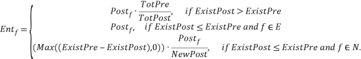
The building RTO’s Transmission Adjusted Market Flow (Entf) is calculated as follows for each Transmission Facility in the non-building RTO’s set of monitored M2M Flowgates f ![]() F:
F:
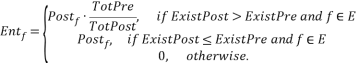
Where:
f represents the relevant Transmission Facility within the building or non-building RTO.
E represents the existing facilities: the set of M2M Flowgates and previously accounted for new or, upgraded or retired Transmission Facilities (which may not be M2M Flowgates) in the relevant (building or non-building) RTO.
N represents the new, or upgraded or retired facilities: the set of Transmission Facilities in the relevant (building or non-building) RTO whose impact on M2M Entitlements is being evaluated.
F represents the set of all Transmission Facilities in the relevant (building or non-building) RTO, including all elements of sets E and N.
Pref is pre-upgrade/retirement market flow on f: the market flow on facility f calculated using the M2M Entitlement assumptions and based on a transmission topology that includes all pre-existing Transmission Facilities and all new, or upgraded or retired Transmission Facilities whose impact on M2M Entitlements has been previously evaluated and incorporated.
Postf is the post-upgrade/retirement market flow on f: the market flow on facility f calculated using the M2M Entitlement assumptions and based on a transmission topology that includes all pre-existing Transmission Facilities and all new, or upgraded or retired Transmission Facilities whose impact on M2M Entitlements has been previously evaluated and incorporated, and all new or, upgraded or retired Transmission Facilities whose impact on M2M Entitlements is being evaluated in the current evaluation step. For Transmission Facility retirements, Postf shall equal zero.
6.4M2M Entitlement Adjustment for a New Set of Generation, Load and Interchange Data
Section 6.3 above addresses how new or upgraded transmission facilitiesTransmission Facilities and Transmission Facility retirements will be reflected in the determination of M2M Entitlements. This section explains how the Parties will update the model used to determine M2M Entitlements to reflect new/updated generation, load and interchange information.
When moving the initial 2009-2011 period generation, interchange and load data forward, the RTOs will need to gather the data specified in Sections 6.1, 6.2 and (where appropriate) 6.3, above for the agreed upon three year period. External Capacity Resources will be included consistent with Section 6.2.1.1, above.
In accordance with the rules specified in Sections 6.1, 6.2 and (where appropriate) 6.3, above, the new set of data will be used to establish a new Reference Year Market Flow. When new or upgraded Transmission Facility or Transmission Facility retirement adjustments are necessary, the new Reference Year Market Flows will be used to determine the New Year and Transmission Adjusted Market Flows based on the rules set forth above. When no new or upgraded Transmission Facility or Transmission Facility retirement adjustments need to be applied, the new Reference Year Market Flows are the basis for the new M2M Entitlements.
7Real-Time Energy Market Coordination
Operation of the Ramapo PARs and redispatch are used by the Parties in real-time operations to effectuate this M2M coordination process. Operation of the Ramapo PARs will permit the Parties to redirect energy to reduce the overall cost of managing transmission congestion and to converge the participating RTOs’ cost of managing transmission congestion. Operation of the Ramapo PARs to manage transmission congestion requires cooperation between the NYISO and PJM. Operation of the Ramapo PARs shall be coordinated with the operation of other PARs at the NYISO – PJM interface.
When a M2M Flowgate that is under the operational control of either NYISO or PJM and that is eligible for redispatch coordination, becomes binding in the Monitoring RTOs real-time security constrained economic dispatch, the Monitoring RTO will notify the Non-Monitoring RTO of the transmission constraint and will identify the appropriate M2M Flowgate that requires redispatch assistance. The Monitoring and Non-Monitoring RTOs will provide the economic value of the M2M Flowgate constraint (i.e., the Shadow Price) as calculated by their respective dispatch models. Using this information, the security-constrained economic dispatch of the Non-Monitoring RTO will include the M2M Flowgate constraint; the Monitoring RTO will evaluate the actual loading of the M2M Flowgate constraint and request that the Non-Monitoring RTO modify its Market Flow via redispatch if it can do so more efficiently than the Monitoring RTO (i.e., if the Non-Monitoring RTO has a lower Shadow Price for that M2M Flowgate than the Monitoring RTO).
An iterative coordination process will be supported by automated data exchanges in order to ensure the process is manageable in a real-time environment. The process of evaluating the Shadow Prices between the RTOs will continue until the Shadow Prices converge and an efficient redispatch solution is achieved. The continual interactive process over the following dispatch cycles will allow the transmission congestion to be managed in a coordinated, cost-effective manner by the RTOs. A more detailed description of this iterative procedure is discussed in Section 7.1 and the appropriate use of this iterative procedure is described in Section 810.
7.1Real-Time Redispatch Coordination Procedures
The following procedure will apply for managing redispatch for M2M Flowgates in the real-time Energy market:
7.1.1M2M Flowgates shall be monitored per each RTO’s internal procedures.
- When (i) an M2M Flowgate is constrained to a defined limit (actual or contingency flow) by a non-transient constraint, and (ii) Market Flows are such that the Non-Monitoring RTO may be able to provide an appreciable amount of redispatch relief to the Monitoring RTO, then the Monitoring RTO shall reflect the monitored M2M Flowgate as constrained.
- M2M Flowgate limits shall be periodically verified and updated.
7.1.2Testing for an Appreciable Amount of Redispatch Relief and Determining the Settlement Market Flow:
When the PARs at the Michigan-Ontario border are not in-service, the ability of the Non-Monitoring RTO to provide an appreciable amount of redispatch relief will be determined by comparing the Non-Monitoring RTO’s Market Flow to the Non-Monitoring RTO M2M Entitlement for the constrained M2M Flowgate. When the Non-Monitoring RTO Market Flow (also the Market Flow used for settlement) is greater than the Non-Monitoring RTO M2M Entitlement for the constrained M2M Flowgate, the Monitoring RTO will assume that an appreciable amount of redispatch relief is available from the Non-Monitoring RTO and will engage the M2M coordination process for the constrained M2M Flowgate.
When any of the PARs at the Michigan-Ontario border are in-service, the ability of the Non-Monitoring RTO to provide an appreciable amount of redispatch relief will be determined by comparing either (i) the Non-Monitoring RTO’s unadjusted Market Flow, or (ii) the Non-Monitoring RTO Market Flow adjusted to reflect the expected impact of the PARs at the Michigan-Ontario border (“LEC Adjusted Market Flow”), to the Non-Monitoring RTO M2M Entitlement for the constrained M2M Flowgate. The rules for determining which Market Flow (unadjusted or adjusted) to compare to the Non-Monitoring RTO M2M Entitlement when any of the PARs at the Michigan-Ontario border are in-service are set forth below.
a.Calculating the Expected Impact of the PARs at the Michigan-Ontario Border on Market Flows
The Non-Monitoring RTO’s unadjusted Market Flow is determined as RTO_MF in accordance with the calculation set forth in Section 5 above. The expected impact of the PARs at the Michigan-Ontario border is determined as follows:
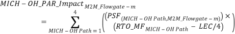
Where:
M2M_Flowgate-m =the relevant M2M Flowgate;
MICH-OH Path =each of the four PAR paths connecting Michigan to Ontario, Canada;
MICH-OH_PAR_ImpactM2M_Flowgate-m =the expected impact of the operation of the PARs at the Michigan-Ontario border on the flow on M2M Flowgate m;
PSF(MICH-OH Path,M2M_Flowgate-m) =the PSF of each of the four Michigan-Ontario PAR paths on M2M Flowgate m;
RTO_MFMICH-OH Path =the Market Flow for each of the four Michigan-Ontario PAR paths, computed in the same manner as the Market Flow is computed for M2M Flowgates in Section 5 above; and
LEC = Actual circulation around Lake Erie as measured by each RTO.
The Non-Monitoring RTO’s LEC Adjusted Market Flow, reflecting the expected impact of the PARs on the Michigan-Ontario border, can be determined by adjusting the RTO_MF from Section 5 to incorporate the MICH-OH_PAR_Impact calculated above.
![]()
Where:
M2M_Flowgate-m =the relevant flowgate;
MICH-OH Path =each of the four PAR paths connecting Michigan to Ontario, Canada;
MICH-OH_PAR_ImpactM2M_Flowgate-m =the expected impact of the operation of the PARs at the Michigan-Ontario border on the flow on M2M Flowgate m;
RTO_MFM2M_Flowgate-m = the Market Flow caused by RTO generation dispatch and transaction scheduling on M2M Flowgate m after accounting for the operation of both the common and non-common PARs; and
LEC Adjusted Market FlowM2M_Flowgate-m = the Market Flow caused by RTO generation dispatch and transaction scheduling on M2M Flowgate m after accounting for the operation of the common PARs, the non-common PARs, and the PARs at the Michigan-Ontario border.
b.Determining Whether to Use Unadjusted Market Flow or LEC Adjusted Market Flow; Determining if Appreciable Redispatch Relief is Available
1) When the Non-Monitoring RTO’s LEC Adjusted Market Flow equals the Non-Monitoring RTO’s unadjusted Market Flow and the Non-Monitoring RTO’s Market Flow (also the Market Flow used for settlement) is greater than the Non-Monitoring RTO M2M Entitlement for the constrained M2M Flowgate, the Monitoring RTO will assume that an appreciable amount of redispatch relief is available from the Non-Monitoring RTO and will engage the M2M coordination process for the constrained M2M Flowgate.
2) When the Non-Monitoring RTO’s unadjusted Market Flow is greater than the Non-Monitoring RTO’s LEC Adjusted Market Flow, then the following calculation shall be performed to determine if an appreciable amount of redispatch relief is expected to be available:
- Determine the minimum of (a) the Non-Monitoring RTO’s unadjusted Market Flow, and (b) the Non-Monitoring RTO’s M2M Entitlement, for the constrained M2M Flowgate; and
- Determine the maximum of (x) the value from step A above, and (y) the Non-Monitoring RTO’s LEC Adjusted Market Flow
When the value from B above (the Market Flow used for settlement), is greater than the Non-Monitoring RTO’s M2M Entitlement for the constrained M2M Flowgate, the Monitoring RTO will assume that an appreciable amount of redispatch relief is available from the Non-Monitoring RTO and will engage the M2M coordination process for the constrained M2M Flowgate.
3) When the Non-Monitoring RTO’s unadjusted Market Flow is less than the Non-Monitoring RTO LEC Adjusted Market Flow, the following calculation shall be performed to determine if an appreciable amount of redispatch relief is expected to be available:
- Determine the maximum of (a) the Non-Monitoring RTO’s unadjusted Market Flow, and (b) the Non-Monitoring RTO M2M Entitlement, for the constrained M2M Flowgate; and
- Determine the minimum of (x) the value from A above, and (y) the Non-Monitoring RTO’s LEC Adjusted Market Flow
When the value from B above (the Market Flow used for settlement), is greater than the Non-Monitoring RTO’s M2M Entitlement for the constrained M2M Flowgate, the Monitoring RTO will assume that an appreciable amount of redispatch relief is available from the Non-Monitoring RTO and will engage the M2M coordination process for the constrained M2M Flowgate.
7.1.3The Monitoring RTO initiates M2M, notifies the Non-Monitoring RTO of the M2M Flowgate that is subject to coordination and updates required information.
7.1.4The Non-Monitoring RTO shall acknowledge receipt of the notification and one of the following shall occur:
- The Non-Monitoring RTO refuses to activate M2M:
- The Non-Monitoring RTO notifies the Monitoring RTO of the reason for refusal; and
- The M2M State is set to “Refused”; or
- The Non-Monitoring RTO agrees to activate M2M:
- Such an agreement shall be considered an initiation of the M2M redispatch process for operational and settlement purposes; and
- The M2M State is set to “Activated”.
7.1.5The Parties have agreed to transmit information required for the administration of this procedure, as per section 35.7.1 of the Agreement.
7.1.6As Shadow Prices converge and approach zero or the Non-Monitoring RTO’s Market Flows and Shadow Prices are such that an appreciable amount of redispatch relief can no longer be provided to the Monitoring RTO, the Monitoring RTO shall be responsible for the continuation or termination of the M2M redispatch process. Current and forecasted future system conditions shall be considered.[1]
When the Monitoring RTO’s Shadow Price is not approaching zero the Monitoring RTO can (1) use the procedure called Testing for an Appreciable Amount of Relief and Determining the Settlement Market Flow from step 2b above, and (2) compare the Non-Monitoring RTO’s Shadow Price to the Monitoring RTO’s Shadow Price, to determine whether there is an appreciable amount of market flow relief being provided.
When the Testing for an Appreciable Amount of Relief and Determining the Settlement Market Flow procedure indicates there is not an appreciable amount of relief being provided, and the Non-Monitoring RTO Shadow Price is not less than the Monitoring RTO Shadow Price, then the Monitoring RTO may terminate the M2M coordination process.
7.1.7Upon termination of M2M, the Monitoring RTO shall
- Notify the Non-Monitoring RTO; and
- Transmit M2M data to the Non-Monitoring RTO with the M2M State set to “Closed”. The timestamp with this transmission shall be considered termination of the M2M redispatch process for operational and settlement purposes.
7.2 Real-Time Ramapo PAR Coordination
The Ramapo PARs will be operated to facilitate interchange schedules while minimizing regional congestion costs. When congestion is not present, the Ramapo PARs will be operated to achieve the target flow as established below in Section 7.2.1.
In order to preserve the long-term availability of the Ramapo PARs, a maximum of 20 taps per PAR per day, and a maximum of 400 taps per calendar month will normally be observed.
7.2.1Ramapo Target Value
A Target Value for flow between the NYISO and PJM shall be determined for each Ramapo PAR (the 3500 PAR and the 4500 PAR) (“TargetRamapo”). These Target Values shall be determined by a formula based on the net interchange schedule between the Parties plus the deviation of actual flows and desired flows across the ABC and JK interfaces and shall be used for settlement purposes as:

Where:
![]() Calculated Target Value for the flow on each Ramapo PAR (PAR3500 and PAR4500);
Calculated Target Value for the flow on each Ramapo PAR (PAR3500 and PAR4500);
![]() 61% of the net interchange schedule between PJM and NYISO over the AC tie lines distributed evenly across the in-service Ramapo PARs; A positive value indicates flows from PJM to NYISO and a negative value indicates flows from NYISO to PJM.
61% of the net interchange schedule between PJM and NYISO over the AC tie lines distributed evenly across the in-service Ramapo PARs; A positive value indicates flows from PJM to NYISO and a negative value indicates flows from NYISO to PJM.
![]() Telemetered real-time flow over the JK interface. A positive value indicates flows from NYISO to PJM and a negative value indicates flows from PJM to NYISO;
Telemetered real-time flow over the JK interface. A positive value indicates flows from NYISO to PJM and a negative value indicates flows from PJM to NYISO;
![]() Telemetered real-time flow over the ABC interface. A positive value indicates flows from PJM to NYISO and a negative value indicates flows from NYISO to PJM.;
Telemetered real-time flow over the ABC interface. A positive value indicates flows from PJM to NYISO and a negative value indicates flows from NYISO to PJM.;
![]() 80% of the telemetered real-time Rockland Electric Company Load;
80% of the telemetered real-time Rockland Electric Company Load;
![]() The JK interface Auto Correction component of the JK interface real-time desired flow as described in Schedule C to the Agreement. A positive value indicates flows from NYISO to PJM and a negative value indicates flows from PJM to NYISO; and
The JK interface Auto Correction component of the JK interface real-time desired flow as described in Schedule C to the Agreement. A positive value indicates flows from NYISO to PJM and a negative value indicates flows from PJM to NYISO; and
![]() The ABC interface Auto Correction component of the ABC interface real-time desired flow as described in Schedule C to the Agreement. A positive value indicates flows from PJM to NYISO and a negative value indicates flows from NYISO to PJM.
The ABC interface Auto Correction component of the ABC interface real-time desired flow as described in Schedule C to the Agreement. A positive value indicates flows from PJM to NYISO and a negative value indicates flows from NYISO to PJM.
In accordance with Appendix 3 of Schedule C to the Agreement, the Participatingparticipating RTOs will mutually agree on the circumstances under which they will allow up to thirteen percent of PJM to New York interchange schedules to flow over the ABC and JK interfaces. When a portion of PJM to New York interchange schedules are allowed to flow over the ABC and JK interfaces, the allowed scheduled interchange will be captured as a change to the ActualJK and ActualABC terms above.
7.2.2Determination of the Cost of Congestion at Ramapo
The incremental cost of congestion relief provided by each Ramapo PAR shall be determined by each of the Parties. These costs shall be determined by multiplying each Party’s Shadow Price on each of its M2M Flowgates by the PSF for each Ramapo PAR for the relevant M2M Flowgates.
The incremental cost of congestion relief provided by each Ramapo PAR shall be determined by the following formula:
![]()
![]()
Where:
![]() Cost of congestion at each Ramapo PAR for the relevant participating RTO
Cost of congestion at each Ramapo PAR for the relevant participating RTO;, where a negative cost of congestion indicates taps in the direction of the relevant participating RTO would alleviate that RTO’s congestion;
![]() Set of M2M Flowgates for the relevant participating RTO;
Set of M2M Flowgates for the relevant participating RTO;
![]() The PSF for each Ramapo PARs on M2M Flowgate–m; and
The PSF for each Ramapo PARs on M2M Flowgate–m; and
![]() The Shadow Price on the relevant participating RTO’s M2M Flowgate m.
The Shadow Price on the relevant participating RTO’s M2M Flowgate m.
7.2.3Desired PAR Changes
Consistent with the congestion cost calculation established in Section 7.2.2 above, if If the NYISO congestion costs associated with the Ramapo PAR are greaterless than the PJM congestion costs associated with the Ramapo PAR, then hold or take taps into NYISO.
Similarly, if If the PJM congestion costs associated with the Ramapo PAR are greaterless than NYISO congestion costs associated with the Ramapo PAR, then hold or take taps into PJM.
Any action on the Ramapo PARs will be coordinated between the Parties and taken into consideration other PAR actions.
8Real-Time Energy Market Settlements
8.1Information Used to Calculate M2M Settlements
For each M2M Flowgate there are two components of the M2M settlement, a redispatch component and a Ramapo PARs coordination component. Both M2M settlement components are defined below.
For the redispatch component, market settlements under this M2M Schedule will be calculated based on the following:
- the Non-Monitoring RTO’s real-time Market Flow, determined in accordance with Section 7.1 above, on each M2M Flowgate compared to its M2M Entitlement for M2M Flowgates eligible for redispatch on each M2M Flowgate; and
- the ex-ante Shadow Price at each M2M Flowgate.
For the Ramapo PARs coordination component, Market settlements under this M2M Schedule will be calculated based on the following:
- actual real-time flow on each of the Ramapo PARs compared to its target flow (TargetRamapo);
- Ramapo PSF for each M2M Flowgate; and
- the ex-ante Shadow Price at each M2M Flowgate.
8.2Real-Time Redispatch Settlement
If the M2M Flowgate is eligible for redispatch, then compute the real-time redispatch settlement for each interval as specified below.
When ![]() ,
,
When ![]() ,
,
Where:
![]() M2M redispatch settlement, in the form of a payment to the Non-Monitoring RTO from the Monitoring RTO, for M2M Flowgate m and interval i;
M2M redispatch settlement, in the form of a payment to the Non-Monitoring RTO from the Monitoring RTO, for M2M Flowgate m and interval i;
![]() M2M redispatch settlement, in the form of a payment to the Monitoring RTO from the Non-Monitoring RTO, for M2M Flowgate m and interval i;
M2M redispatch settlement, in the form of a payment to the Monitoring RTO from the Non-Monitoring RTO, for M2M Flowgate m and interval i;
![]() real-time RTO_MF, determined for settlement in accordance with Section 7.1 above, for M2M Flowgate m and interval i;
real-time RTO_MF, determined for settlement in accordance with Section 7.1 above, for M2M Flowgate m and interval i;
![]() Non-Monitoring RTO M2M Entitlement for M2M Flowgate m and interval i;
Non-Monitoring RTO M2M Entitlement for M2M Flowgate m and interval i;
![]() Monitoring RTO’s Shadow Price for M2M Flowgate m and interval i;
Monitoring RTO’s Shadow Price for M2M Flowgate m and interval i; and
![]() Non-Monitoring RTO’s Shadow Price for M2M Flowgate m
Non-Monitoring RTO’s Shadow Price for M2M Flowgate m. and interval i; and
![]() number of seconds in interval i.
number of seconds in interval i.
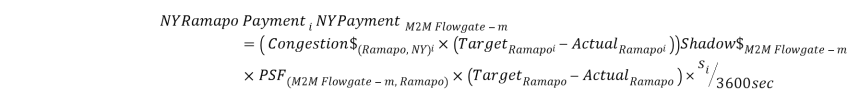
8.3Ramapo PARs Settlement
For each M2M Flowgate, computeCompute the real-time Ramapo PAR settlement for each interval as specified below.
For each M2M Flowgate, when When ![]() ,
,
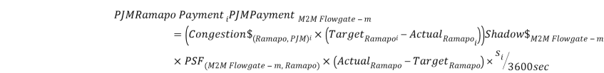
For each M2M Flowgate, when When ![]() ,
,
Where:
![]() Measured real-time actual flow on each of the Ramapo PARs for interval i. For purposes of this equation, a positive value indicates a flow from PJM to the NYISO;
Measured real-time actual flow on each of the Ramapo PARs for interval i. For purposes of this equation, a positive value indicates a flow from PJM to the NYISO;
![]() Calculated Target Value for the flow on each Ramapo PAR (PAR3500 and PAR4500) as described in Section 7.2.1 above for interval i. For purposes of this equation, a positive value indicates a flow from PJM to the NYISO;
Calculated Target Value for the flow on each Ramapo PAR (PAR3500 and PAR4500) as described in Section 7.2.1 above for interval i. For purposes of this equation, a positive value indicates a flow from PJM to the NYISO;
![]()
Shadow Price, as computed by the payee, for M2M Flowgate m;
![]()
The PSF for each Ramapo PARs for M2M Flowgate m;
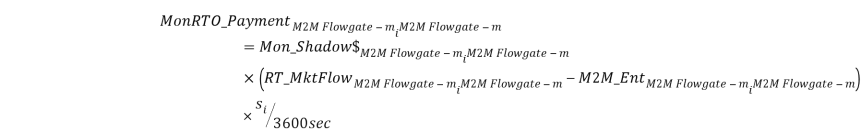
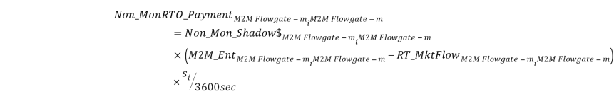
![]() PJM Ramapo PARs settlement,
PJM Ramapo PARs settlement, in the form of defined as a payment to PJM from the NYISO, for M2M Flowgate m; to PJM when the value is positive, and a payment from PJM to the NYISO when the value is negative for interval i;
![]() NYISO Ramapo PARs settlement,
NYISO Ramapo PARs settlement, in the formdefined as a payment to NYISO from PJM, for M2M Flowage m; to the NYISO when the value is negative, and a payment from the NYISO to PJM when the value is positive for interval i;
![]() Cost of congestion at each Ramapo PAR for PJM, calculated in accordance with Section 7.2.2 above for interval i;
Cost of congestion at each Ramapo PAR for PJM, calculated in accordance with Section 7.2.2 above for interval i;
![]() Cost of congestion at each Ramapo PAR for NY, calculated in accordance with Section 7.2.2 above for interval i, and
Cost of congestion at each Ramapo PAR for NY, calculated in accordance with Section 7.2.2 above for interval i, and
![]() number of seconds in interval i.
number of seconds in interval i.
8.4Calculating a Combined M2M Settlement
The M2M settlement for each M2M Flowgate shall be the sum of the real-time redispatch settlement for each M2M Flowgate and the Ramapo PARs settlement for each interval
If NYISO is the Monitoring RTO for the M2M Flowgate:

If PJM is the Monitoring RTO for the M2M Flowgate:

Where:
![]() M2M NYISO settlement, defined as a payment from PJM to NYISO when the value is positive, and a payment from the NYISO to PJM when the value is negative for interval i;
M2M NYISO settlement, defined as a payment from PJM to NYISO when the value is positive, and a payment from the NYISO to PJM when the value is negative for interval i;
![]() M2M PJM settlement, defined as a payment from NYISO to PJM when the value is positive, and a payment from the PJM to NYISO when the value is negative for interval i;
M2M PJM settlement, defined as a payment from NYISO to PJM when the value is positive, and a payment from the PJM to NYISO when the value is negative for interval i;
![]() Monitoring RTO payment to Non-Monitoring RTO for congestion on M2M Flowgate m for interval i; and
Monitoring RTO payment to Non-Monitoring RTO for congestion on M2M Flowgate m for interval i; and
![]() Non-Monitoring RTO payment to Monitoring RTO for congestion on M2M Flowgate m for interval i.
Non-Monitoring RTO payment to Monitoring RTO for congestion on M2M Flowgate m for interval i.

Where:
![]() M2M settlement, defined as a payment from the
M2M settlement, defined as a payment from the Non-Monitoring RTO to the Monitoring RTO, NYISO to PJM when the value is positive, and a payment from PJM to the NYISO when the value is negative for interval i; and
![]() M2M NYISO settlement, defined as a payment from PJM to NYISO when the value is positive, and a payment from the NYISO to PJM when the value is negative for interval i;
M2M NYISO settlement, defined as a payment from PJM to NYISO when the value is positive, and a payment from the NYISO to PJM when the value is negative for interval i;
![]() M2M PJM settlement, defined as a payment from NYISO to PJM when the value is positive, and a payment from the PJM to NYISO when the value is negative for interval i;
M2M PJM settlement, defined as a payment from NYISO to PJM when the value is positive, and a payment from the PJM to NYISO when the value is negative for interval i;
![]()
Non-Monitoring RTO payment to Non-Monitoring RTO for congestion on M2M Flowgate m for interval i;
![]()
Non-Monitoring RTO payment to Non-Monitoring RTO for congestion on M2M Flowgate m for interval i;
![]() PJM Ramapo PARs settlement,
PJM Ramapo PARs settlement, in the form of defined as a payment to PJM from the NYISO to PJM when the value is positive, and a payment from PJM to the NYISO when the value is negative, for M2M Flowgate m for interval i; and
![]() NYISO Ramapo PARs settlement,
NYISO Ramapo PARs settlement, in the form ofdefined as a payment to NYISO from PJM to the NYISO when the value is negative and a payment from the NYISO to PJM when the value is positive, for M2M Flowgate m for interval i.; and si = number of seconds in interval i.
For the purpose of settlements calculations, each interval will be calculated separately and then integrated to an hourly value:
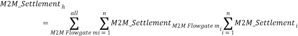
Where:
![]() M2M settlement for hour h; and
M2M settlement for hour h; and
n = Number of intervals in hour h.
Section 10.1 of this M2M Schedule sets forth circumstances under which the M2M coordination process and M2M settlements may be temporarily suspended.
9When One of the RTOs Does Not Have Sufficient Redispatch
Under the normal M2M coordination process, sufficient redispatch for a M2M Flowgate may be available in one RTO but not the other. When this condition occurs, in order to ensure an operationally efficient dispatch solution is achieved, the RTO without sufficient redispatch will redispatch all effective generation to control the M2M Flowgate to a “relaxed” Shadow Price limit. Then this RTO calculates the Shadow Price for the M2M Flowgate using the available redispatch which is limited by the maximum physical control action inside the RTO. Because the magnitude of the Shadow Price in this RTO cannot reach that of the other RTO with sufficient redispatch, unless further action is taken, there will be a divergence in Shadow Prices and the LMPs at the RTO border.
Subject to Section 10.1.2 below, a A special process is designed to enhance the price convergence under this condition. If the Non‑Monitoring RTO cannot provide sufficient relief to reach the Shadow Price of the Monitoring RTO, the constraint relaxation logic will be deactivated. The Non-Monitoring RTO will then be able to use the Monitoring RTO’s Shadow Price without limiting the Shadow Price to the maximum Shadow Price associated with a physical control action inside the Non-Monitoring RTO. With the M2M Flowgate Shadow Prices being the same in both RTOs, their resulting bus LMPs will converge in a consistent price profile.
10Appropriate Use of the M2M Coordination Process
Under normal operating conditions, the Parties will model all M2M Flowgates in their respective real-time EMSs. M2M Flowgates will be controlled using M2M tools for coordinated redispatch and coordinated operation of the Ramapo PARs, and will be eligible for M2M settlements.
10.1Qualifying Conditions for M2M Settlement
10.1.1 Purpose of M2M. M2M was established to address regional, not local issues. The intent is to implement the M2M coordination process and settle on such coordination where both Parties have significant impact.
10.1.2 Minimizing Less than Optimal Dispatch. The Parties agree that, as a general matter, they should minimize financial harm to one RTO that results from the M2M coordination process initiated by the other RTO that produces less than optimal dispatch.
10.1.3 Use M2M Whenever Binding a M2M Flowgate. During normal operating conditions, the M2M redispatch process will be initiated by the Monitoring RTO whenever an M2M Flowgate that is eligible for redispatch is constrained and therefore binding in its dispatch. Coordinated operation of the Ramapo PARs is the default condition and does not require initiation by either Party to occur.
10.1.4 Most Limiting Flowgate. Generally, controlling to the most limiting Flowgate provides the preferable operational and financial outcome. In principle and as much as practicable, the M2M coordination process will take place on the most limiting Flowgate, and to that Flowgate’s actual limit (thermal, reactive, stability).
10.1.5 Abnormal Operating Conditions.
- A Party that is experiencing system conditions that require the system operators’ immediate attention may temporarily delay implementation of the M2M redispatch process or cease an active M2M redispatch event until a reasonable time after the system condition that required the system operators’ immediate attention is resolved.
- Either Party may temporarily suspend an active M2M coordination process or delay implementation of the M2M coordination process if a Party is experiencing, or acting in good faith suspects it may be experiencing, (1) a failure or outage of the data link between the Parties prevents the exchange of accurate or timely real-time data necessary to implement the M2M coordination process; or (2) a failure or outage of any computational or data systems preventing the actual or accurate calculation of data necessary to implement the M2M coordination process. The Parties shall resolve the issue causing the failure or outage of the data link, computational systems, or data systems as soon as possible in accordance with Good Utility Practice. The Parties shall resume implementation of the M2M coordination process following the successful testing of the data link or relevant system(s) after the failure or outage condition is resolved.
10.1.6 Transient System Conditions. A Party that is experiencing intermittent congestion due to transient system conditions including, but not limited to, interchange ramping or transmission switching, is not required to implement the M2M redispatch process unless the congestion continues after the transient condition(s) have concluded.
10.1.7 Temporary Cessation of M2M Coordination Process Pending Review.
If the net charges to a Party resulting from implementation of the M2M coordination process for a market-day exceed five hundred thousand dollars, then the Party that is responsible for paying the charges may (but is not required to) suspend implementation of this M2M coordination process (for a particular M2M Flowgate, or of the entire M2M coordination process) until the Parties are able to complete a review to ensure that both the process and the calculation of settlements resulting from the M2M coordination process are occurring in a manner that is both (a) consistent with this M2M Coordination Schedule, and (b) producing a just and reasonable result. The Party requesting suspension must identify specific concerns that require investigation within one business day of requesting suspension of the M2M coordination process. If, following their investigation, the Parties mutually agree that the M2M coordination process is (i) being implemented in a manner that is consistent with this M2M Coordination Schedule and (ii) producing a just and reasonable result, then the M2M coordination process shall be re-initiated as quickly as practicable. If the Parties are unable to mutually agree that the M2M coordination process was being implemented appropriately, or of the Parties are unable to mutually agree that the M2M coordination process was producing a just and reasonable result, the suspension (for a particular M2M Flowgate, or of the entire M2M coordination process) shall continue while the Parties engage in dispute resolution in accordance with section 35.15 of the Agreement.
10.1.8Suspension of M2M Settlement when a Request for Taps on Common PARs to Prevent Overuse is Refused. If a Party requests that taps be taken on any Common PAR to reduce the requesting Party’s overuse of the other Party’s transmission system, refusal by the other Party or its Transmission Owner(s) to permit taps to be taken to reduce overuse shall result in the Ramapo PAR settlement component of M2M (see Section 8.3 above) being suspended for the requesting Party until the tap request is granted. The refusing Party shall not be relieved of any of its M2M settlement obligations.
10.1.9Suspension of Ramapo PAR Settlement due to Transmission Facility Outage(s). The Parties shall suspend Ramapo PAR settlements when: (a) the Branchburg – Ramapo 500kV 5018 transmission line is out of service; or (b) there is a simultaneous outage of Ramapo PAR3500 and Ramapo PAR4500; or (c) the occurrence of both 10.1.9(a) and 10.1.9(b).
No other Transmission Facility outage(s) will trigger suspension of Ramapo PAR settlements under this section 10.1.9.
10.2After-the-Fact Review to Determine M2M Settlement
Based on the communication and data exchange that has occurred in real-time between the Parties, there will be an opportunity to review the use of the market-to-marketM2M coordination process to verify it was an appropriate use of the M2M coordination process and subject to M2M settlement. The Parties will initiate the review as necessary to apply these conditions and settlements adjustments. The Parties will cooperate to review the data exchanged and used to determine M2M settlements and will mutually identify and resolve errors and anomalies in the calculations that determine the M2M settlements.
If the data exchanged for the M2M redispatch process was relied on by the Non-Monitoring RTO’s dispatch to determine the shadow cost the Non-Monitoring RTO was dispatching to when providing relief at an M2M Flowgate, the data transmitted by the Monitoring RTO that was used to determine the Non-Monitoring RTO’s shadow cost shall not be modified except by mutual agreement prior to calculating M2M settlements. Any necessary corrections to the data exchange shall be made for future M2M coordination.
10.3 Access to Data to Verify Market Flow Calculations
Each Party shall provide the other Party with data to enable the other Party independently to verify the results of the calculations that determine the M2M settlements under this M2M Coordination Schedule. A Party supplying data shall retain that data for two years from the date of the settlement invoice to which the data relates, unless there is a legal or regulatory requirement for a longer retention period. The method of exchange and the type of information to be exchanged pursuant to section 35.7.1 of the Agreement shall be specified in writing. The Parties will cooperate to review the data and mutually identify or resolve errors and anomalies in the calculations that determine the M2M settlements. If one Party determines that it is required to self report a potential violation to the Commission’s Office of Enforcement regarding its compliance with this M2M Coordination Schedule, the reporting Party shall inform, and provide a copy of the self report to, the other Party. Any such report provided by one Party to the other shall be Confidential Information.
11M2M Change Management Process
11.1Notice
Prior to changing any process that implements this M2M Schedule, the Party desiring the change shall notify the other Party in writing or via email of the proposed change. The notice shall include a complete and detailed description of the proposed change, the reason for the proposed change, and the impacts the proposed change is expected to have on the implementation of the M2M coordination process, including M2M settlements under this M2M Schedule.
11.2Opportunity to Request Additional Information
Following receipt of the Notice described in Section 1011.1, the receiving partyParty may make reasonable requests for additional information/documentation from the other Party. Absent mutual agreement of the partiesParties, the submission of a request for additional information under this Section shall not delay the obligation to timely note any objection pursuant to Section 1011.3, below.
11.3Objection to Change
Within ten business days after receipt of the Notice described in Section 1011.1 (or within such longer period of time as the partiesParties mutually agree), the receiving Party may notify in writing or via email the other Party of its disagreement with the proposed change. Any such notice must specifically identify and describe the concern(s) that required the receiving partyParty to object to the described change.
11.4Implementation of Change
The Party proposing a change to its implementation of the M2M coordination process shall not implement such change until (a) it receives written or email notification from the other Party that the other Party concurs with the change, or (b) the ten business day notice period specified in Section 1011.3 expires, or (c) completion of any dispute resolution process initiated pursuant to this Agreement.
Effective Date: 8/14/2013 - Docket #: ER13-1684-000 - Page 1