NYISO Tariffs --> Open Access Transmission Tariff (OATT) --> 38 OATT Attachment FF - Generator Deactivation Process --> 38.22-38.23 OATT Att FF Generator Deactivation Process
38.22 Cost Allocation Methodology for Short-Term Reliability Process
The cost allocation mechanism under this Section 38.22 sets forth the basis for allocating costs associated with: (i) a Responsible Transmission Owner’s transmission Short-Term Reliability Process Solution proposed in accordance with Section 38.4 and, if applicable, its conceptual permanent transmission Short-Term Reliability Process Solution, (ii) a Developer’s transmission Short-Term Reliability Process Solution selected by the ISO to address a Short-Term Reliability Process Need pursuant to Section 38.10, or (iii) a Generator operating under an RMR Agreement to address a Short-Term Reliability Process Need. The ISO shall implement the specific cost allocation methodology set forth in this Section 38.22 of this Attachment FF in accordance with the Order No. 1000 Regional Cost Allocation Principles as set forth in Section 31.5.2.1 of Attachment Y.
The formula is applicable to the ISO’s share of the costs of an Interregional Transmission Project proposed as a regulated transmission solution to an identified Short Term Reliability Process Need in accordance with Section 38.4.2.5 of Attachment FF. The formula is not applicable to that portion of the cost of a regulated transmission reliability project that is, pursuant to, as applicable, Section 25.7.12 of Attachment S or Section 40.13.12 of Attachment HH to the ISO OATT, paid for with funds (1) previously committed by or collected from Interconnection CustomersDevelopers through their acceptance of a Project Cost Allocation for System Deliverability Upgrades required for the interconnection of generation projects, or Class Year Transmission Projects, or Cluster Study Transmission Projects, or (2) funds collected as a Highway Facilities Charge pursuant to Rate Schedule 12 of the ISO OATT.
This Section 38.22 establishes the allocation of the costs related to resolving Short-Term Reliability Process Needs resulting from resource adequacy, BPTF thermal transmission security, local transmission security for a Generator Deactivation Reliability Need, dynamic stability, and short circuit issues. Costs will be allocated in accordance with the following hierarchy: (i) resource adequacy pursuant to Section 38.22.1, (ii) BPTF thermal transmission security pursuant to Section 38.22.2, (iii) BPTF voltage security pursuant to Section 38.22.3, (iv) local transmission security for a Generator Deactivation Reliability Need pursuant to Section 38.22.4, (v) dynamic stability pursuant to Section 38.22.5, and (vi) short circuit pursuant to Section 38.22.6.
38.22.1 Resource Adequacy Reliability Solution Cost Allocation Formula
For purposes of solutions eligible for cost allocation under this Section 38.22, this section sets forth the cost allocation methodology applicable to that portion of the costs of the solution attributable to resolving resource adequacy. The same cost allocation formula is applied regardless of the project or sets of projects being triggered; however, the nature of the solution set may lead to some terms equaling zero, thereby dropping out of the equation. To ensure that appropriate allocation to the LCR and non-LCR zones occurs, the zonal allocation percentages are developed through a series of steps that first identify responsibility for LCR deficiencies, followed by responsibility for remaining need. The following formula shall apply to the allocation of the costs of the solution attributable to resource adequacy:
|
|
| + |
|
| * |
|
|
|
|
|
|
|
|
| ||||||
|
|
|
|
|
|
|
|
|
|
|
|
|
| + |
|
| * |
|
|
| *100% |
|
|
|
|
|
Where i is for each applicable zone, n represent the total zones in NYCA, m represents the zones isolated by the binding interfaces, IRM is the statewide reserve margin, and where LCR is defined as the locational capacity requirement in terms of percentage and is equal to zero for those zones without an LCR requirement, LCRdefi is the applicable zonal LCR deficiency, SolnSTWdef is the STWdef for each applicable project, SolnCIdef is the CIdef for each applicable project, and Soln_Size represents the total compensatory MW addressed by each applicable project for all reliability cost allocation steps in this Section 38.22.
Three step cost allocation methodology for regulated reliability solutions:
38.22.1.1Step 1 - LCR Deficiency
38.22.1.1.1Any deficiencies in meeting the LCRs for the Target Year will be referred to as the LCRdef. If the reliability criterion is met once the LCR deficiencies have been addressed, that is LOLE 0.1 for the Target Year is achieved, then the only costs allocated will be those related to the LCRdef MW. Cost responsibility for the LCRdef MW will be borne by each deficient locational zone(s), to the extent each is individually deficient.
For a single solution that addresses only an LCR deficiency in the applicable LCR zone, the equation would reduce to:
![]()
Where i is for each applicable LCR zone, LCRdefi represents the applicable zonal LCR deficiency, and Soln_Size represents the total compensatory MW addressed by the applicable project.
38.22.1.1.2Prior to the LOLE calculation, voltage constrained interfaces will be recalculated to determine the resulting transfer limits when the LCRdef MW are added.
38.22.1.2Step 2 - Statewide Resource Deficiency. If the reliability criterion is not met after the LCRdef has been addressed, that is an LOLE > 0.1, then a NYCA Free Flow Test will be conducted to determine if NYCA has sufficient resources to meet an LOLE of 0.1.
38.22.1.2.1If NYCA is found to be resource limited, the ISO, using the transfer limits and resources determined in Step 1, will determine the optimal distribution of additional resources to achieve a reduction in the NYCA LOLE to 0.1.
38.22.1.2.2Cost allocation for compensatory MW added for cost allocation purposes to achieve an LOLE of 0.1, defined as a Statewide MW deficiency (STWdef), will be prorated to all NYCA zones, based on the NYCA coincident peak load. The allocation to locational zones will take into account their locational requirements.
For a single solution that addresses only a statewide deficiency, the equation would reduce to:
|
|
| * |
|
| *100% |
|
|
| ||||
|
|
|
|
|
|
|
Where i is for each applicable zone, n is for the total zones in NYCA, IRM is the statewide reserve margin, and LCR is defined as the locational capacity requirement in terms of percentage and is equal to zero for those zones without an LCR requirement, Soln STWdef is the STWdef for the applicable project, and Soln_Size represents the total compensatory MW addressed by the applicable project.
38.22.1.3Step 3 - Constrained Interface Deficiency. If the NYCA is not resource limited as determined by the NYCA Free Flow Test, then the ISO will examine constrained transmission interfaces, using the Binding Interface Test.
38.22.1.3.1The ISO will provide output results of the reliability simulation program utilized for the RNA that indicate the hours that each interface is at limit in each flow direction, as well as the hours that coincide with a loss of load event. These values will be used as an initial indicator to determine the binding interfaces that are impacting LOLE within the NYCA.
38.22.1.3.2The ISO will review the output of the reliability simulation program utilized for the RNA along with other applicable information that may be available to make the determination of the binding interfaces.
38.22.1.3.3Bounded Regions are assigned cost responsibility for the compensatory MW, defined as CIdef, needed to reach an LOLE of 0.1.
38.22.1.3.4If one or more Bounded Regions are isolated as a result of binding interfaces identified through the Binding Interface Test, the ISO will determine the optimal distribution of compensatory MW to achieve a NYCA LOLE of 0.1. Compensatory MW will be added until the required NYCA LOLE is achieved.
38.22.1.3.5The Bounded Regions will be identified by the ISO’s Binding Interface Test, which identifies the bounded interface limits that can be relieved and have the greatest impact on NYCA LOLE. The Bounded Region that will have the greatest benefit to NYCA LOLE will be the area to be first allocated costs in this step. The ISO will determine if after the first addition of compensating MWs the Bounded Region with the greatest impact on LOLE has changed. During this iterative process, the Binding Interface Test will look across the state to identify the appropriate Bounded Region. Specifically, the Binding Interface Test will be applied starting from the interface that has the greatest benefit to LOLE (the greatest LOLE reduction per interface compensatory MW addition), and then extended to subsequent interfaces until a NYCA LOLE of 0.1 is achieved.
38.22.1.3.6The CIdef MW are allocated to the applicable Bounded Region isolated as a result of the constrained interface limits, based on their NYCA coincident peaks. Allocation to locational zones will take into account their locational requirements.
For a single solution that addresses only a binding interface deficiency, the equation would reduce to:
|
|
| * |
|
| *100% |
|
|
| ||||
|
|
|
|
|
|
|
Where i is for each applicable zone, m is for the zones isolated by the binding interfaces, IRM is the statewide reserve margin, and where LCR is defined as the locational capacity requirement in terms of percentage and is equal to zero for those zones without an LCR requirement, SolnCIdef is the CIdef for the applicable project and Soln_Size represents the total compensatory MW addressed by the applicable project.
38.22.2BPTF Thermal Transmission Security Cost Allocation Formula
For purposes of solutions eligible for cost allocation under this Section 38.22, this section sets forth the cost allocation methodology applicable to that portion of the costs of the solution attributable to resolving BPTF thermal transmission security issues. If, after consideration of the compensatory MW identified in the resource adequacy reliability solution cost allocation in accordance with Section 38.22.1, there remains a BPTF thermal transmission security issue, the ISO will allocate the costs of the portion of the solution attributable to resolving the BPTF thermal transmission security issue(s) to the Subzones that contribute to the BPTF thermal transmission security issue(s) in the following manner.
38.22.2.1Calculation of Nodal Distribution Factors
The ISO will calculate the nodal distribution factor for each load bus modeled in the power flow case utilizing the output of the reliability simulation program that identified the Short-Term Reliability Process Need, including the NYCA generation dispatch and NYCA coincident peak Load. The nodal distribution factor represents the percentage of the Load that flows across the facility subject to the Short-Term Reliability Process Need. The sign (positive or negative) of the nodal distribution factor represents the direction of flow.
38.22.2.2Calculation of Nodal Flow
The ISO will calculate the nodal megawatt flow, defined as Nodal Flow, for each load bus modeled in the power flow case by multiplying the amount of Load in megawatts for the bus, defined as Nodal Load, by the nodal distribution factor for the bus. Nodal Flow represents the number of megawatts that flow across the facility subject to the Short-Term Reliability Process Need due to the Load.
38.22.2.3Calculation of Contributing Load and Contributing Flow
The Nodal Load for a load bus with a positive nodal distribution factor is a contributing Load, defined as CLoad, and the Nodal Flow for that Load is contributing flow, defined as CFlow. To identify contributing Loads that have a material impact on the Short-Term Reliability Process Need, the ISO will calculate a contributing materiality threshold, defined as CMT, as follows:
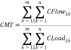
Where m is for the total number of Subzones and n is for the total number of load buses in a given Subzone.
38.22.2.4Calculation of Helping Load and Helping Flow
The Nodal Load for a load bus with a negative or zero nodal distribution factor is a helping Load, defined as HLoad, and the Nodal Flow for that Load is helping flow, defined as HFlow. To identify helping Loads that have a material impact on the Short-Term Reliability Process Need, the ISO will calculate a helping materiality threshold, defined as HMT, as follows:
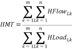
Where m is for the total number of Subzones and n is for the total number of load buses in a given Subzone.
38.22.2.5Calculation of Net Material Flow for Each Subzone
The ISO will identify material Nodal Flow for each Subzone and calculate the net material flow for each Subzone. For each load bus, the Nodal Flow will be identified as material flow, defined as MFlow, if the nodal distribution factor is (i) greater than or equal to CMT, or (ii) less than or equal to HMT. The net material flow for each Subzone, defined as SZ_NetFlow, is calculated as follows:
![]()
Where j is for each Subzone and n is for the total number of load buses in a given Subzone.
38.22.2.6Identification of Allocated Flow for Each Subzone
The ISO will identify the allocated flow for each Subzone and verify that sufficient contributing flow is being allocated costs. For each Subzone, if the SZ_NetFlow is greater than zero, that Subzone has a net material contribution to the Short-Term Reliability Process Need and the SZ_NetFlow is identified as allocated flow, defined as SZ_AllocFlow. If the SZ_NetFlow is less than or equal to zero, that Subzone does not have a net material contribution to the Generator Deactivation Reliability Need and the SZ_AllocFlow is zero for that Subzone. If the total SZ_AllocFlow for all Subzones is less than 60% of the total CFlow for all Subzones, then the CMT will be reduced and SZ_NetFlow recalculated until the total SZ_AllocFlow for all Subzones is at least 60% of the total CFlow for all Subzones.
38.22.2.7Cost Allocation for a Single BPTF Thermal Transmission Security Issue
For a single solution that addresses only a BPTF thermal transmission security issue, the equation for cost allocation would reduce to:
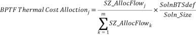
Where j is for each Subzone; m is for the total number of Subzones; SZ_AllocFlow is the allocated flow for each Subzone; SolnBTSdef is the number of compensatory MW for the BPTF thermal transmission security issue for the applicable project; and Soln_Size represents the total compensatory MW addressed by the applicable project.
38.22.2.8Cost Allocation for Multiple BPTF Thermal Transmission Security Issues
If a single solution addresses multiple BPTF thermal transmission security issues, the ISO will calculate weighting factors based on the ratio of the present value of the estimated costs for individual solutions to each BPTF thermal transmission security issue. The present values of the estimated costs for the individual solutions shall be based on a common base date that will be the beginning of the calendar month in which the cost allocation analysis is performed (the “Base Date”). The ISO will apply the weighting factors to the cost allocation calculated for each Subzone for each individual BPTF thermal transmission security issue. The following example illustrates the cost allocation for such a solution:
- A cost allocation analysis for the selected solution is to be performed during a given month establishing the beginning of that month as the Base Date.
- The ISO has identified two BPTF thermal transmission security issues, Overload X and Overload Y, and the ISO has selected a single solution (Project Z) to address both BPTF thermal transmission security issues.
- The cost of a solution to address only Overload X (Project X) is Cost(X), provided in a given year’s dollars. The number of years from the Base Date to the year associated with the cost estimate of Project (X) is N(X).
- The cost of a solution to address only Overload Y (Project Y) is Cost(Y), provided in a given year’s dollars. The number of years from the Base Date to the year associated with the cost estimate of Project Y is N(Y).
- The discount rate, D, to be used for the present value analysis shall be the current after-tax weighted average cost of capital for the Transmission Owners.
- Based on the foregoing assumptions, the following formulas will be used:
- Present Value of Cost (X) = PV Cost (X) = Cost (X) / (1+D)N(X)
- Present Value of Cost (Y) = PV Cost (Y) = Cost (Y) / (1+D)N(Y)
- Overload X weighting factor = PV Cost (X)/[PV Cost (X) + PV Cost (Y)]
- Overload Y weighting factor = PV Cost (Y)/[PV Cost (X) + PV Cost (Y)]
- Applying those formulas, if:
Cost (X) = $100 Million and N(X) = 6.25 years
Cost (Y) = $25 Million and N(Y) = 4.75 years
D = 7.5% per year
Then:
PV Cost (X) = 100/(1+0.075) 6.25 = 63.635 Million
PV Cost (Y) = 25/(1+0.075)4.75 = 17.732 Million
Overload X weighting factor = 63.635 / (63.635 + 17.732) = 78.21%
Overload Y weighting factor = 17.732 / (63.635 + 17.732) = 21.79%
- Applying those weighing factors, if:
Subzone A cost allocation for Overload X is 15%
Subzone A cost allocation for Overload Y is 70%
Then:
Subzone A cost allocation % for Project Z =
(15% * 78.21%) + (70% * 21.79%) = 26.99%
38.22.2.9Exclusion of Subzone(s) Based on De Minimis Impact
If a Subzone is assigned a BPTF thermal transmission security cost allocation less than a de minimis dollar threshold of the total project costs, that Subzone will not be allocated costs; provided however, that the total de minimis Subzones may not exceed 10% of the total BPTF thermal transmission security cost allocation. The de minimis threshold is initially $10,000. If the total allocation percentage of all de minimis Subzones is greater than 10%, then the de minimis threshold will be reduced until the total allocation percentage of all de minimis Subzones is less than or equal to 10%.
38.22.3BPTF Voltage Security Cost Allocation
If, after consideration of the compensatory MW identified in the resource adequacy cost allocation in accordance with Section 38.22.1 and BPTF thermal transmission security cost allocation in accordance with Section 38.22.2, there remains a BPTF voltage security issue, the ISO will allocate the costs of the portion of the solution attributable to resolving the BPTF voltage security issue(s) to the Subzones that contribute to the BPTF voltage security issue(s). The cost responsibility for the portion (MW or MVAr) of the solution attributable to resolving the BPTF voltage security issue(s), defined as SolnBVSdef, will be allocated on a Load-ratio share to each Subzone to which each bus with a voltage issue is connected, as follows:
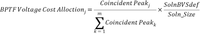
Where j is for each Subzone; m is for the total number of Subzones that are subject to BPTF voltage cost allocation; Coincident Peak is for the total peak Load for each Subzone; SolnBVSdef is for the portion of the solution necessary to resolve the BPTF voltage security issue(s); and Soln_Size represents the total compensatory MW addressed by the applicable project.
38.22.4Local Transmission Security Cost Allocation
If, after consideration of the compensatory MW identified in the resource adequacy cost allocation in accordance with Section 38.22.1, the BPTF thermal transmission security cost allocation in accordance with Section 38.22.2, and BPTF voltage security cost allocation in accordance with Section 38.22.3, there remains a non-BPTF thermal security issue or a non-BPTF voltage security issue, the ISO will allocate the costs of resolving the local security issue(s) to the Subzones that contribute to the local security issue(s). This local transmission security step will only apply for the allocation of the costs of a Short-Term Reliability Process Solution to a Generator Deactivation Reliability Need.
38.22.4.1The Subzone in which the receiving terminal of the non-BPTF facility is located is assigned cost responsibility for the megawatt portion of the solution needed to eliminate the non-BPTF thermal issue(s), defined as LocalThermalMW. If multiple non-BPTF thermal issues in multiple Subzones are addressed by the solution, the LocalThermalMW will be allocated on a Load-ratio share to each identified Subzone as follows:

Where j is for each Subzone; m is for the total number of Subzones that are subject to local thermal cost allocation; Coincident Peak is for the total peak load for each Subzone; LocalThermalMW is for the megawatt portion of the solution needed to eliminate the non-BPTF thermal issue(s); and Soln_Size represents the total compensatory MW addressed by the solution.
38.22.4.2If there remains a voltage issue after consideration of LocalThermalMW, then the cost responsibility for the megawatt portion of the solution necessary to resolve the voltage issue(s), defined as LocalVoltageMW, will be allocated on a Load-ratio share to each Subzone to which each bus with a voltage issue is connected, as follows:
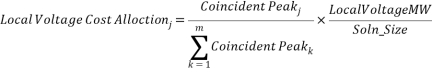
Where j is for each Subzone; m is for the total number of Subzones that are subject to local voltage cost allocation; Coincident Peak is for the total peak Load for each Subzone; LocalVoltageMW is for the megawatt portion of the RMR Agreement necessary to resolve the voltage issue(s); and Soln_Size represents the total compensatory MW addressed by the solution.
38.22.5Dynamic Stability Cost Allocation
If, after consideration of the compensatory MW identified in the resource adequacy cost allocation in accordance with Section 38.22.1, BPTF thermal transmission security cost allocation in accordance with Section 38.22.2, BPTF voltage security cost allocation in accordance with Section 38.22.3, and local transmission security cost allocation for a Generator Deactivation Reliability Need in accordance with Section 38.22.4, there remains a dynamic stability issue, the ISO will allocate the costs of the portion of the solution attributable to resolving the dynamic stability issue(s) to all Subzones in the NYCA on a Load-ratio share basis, as follows:
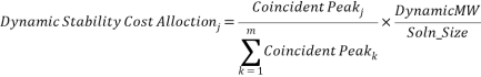
Where j is for each Subzone; m is for the total number of Subzones; Coincident Peak is for the total peak Load for each Subzone; DynamicMW is for the megawatt portion of the solution necessary to resolve the dynamic stability issue(s) for the applicable project; and Soln_Size represents the total compensatory MW addressed by the applicable project.
38.22.6Short Circuit Issues
If, after the completion of the prior reliability cost allocation steps, there remains a short circuit issue, the short circuit issue will be deemed a local issue and related costs will not be allocated under this process.
38.23Cost Recovery for Short-Term Reliability Process
38.23.1The Responsible Transmission Owner or the Developer that proposes a transmission Short-Term Reliability Process Solution that is selected by the ISO pursuant to Section 38.10 to address a Short-Term Reliability Process Need shall be entitled to full recovery of all reasonably incurred costs, including a reasonable return on investment and any applicable incentives, related to the development, construction, operation and maintenance of the transmission Short-Term Reliability Process Solution. The Responsible Transmission Owner shall also be entitled to recover its costs for developing its proposed transmission Short-Term Reliability Process Solution and, if applicable, its conceptual permanent Short-Term Reliability Process Solution, whether or not such solutions were selected by the ISO. The Responsible Transmission Owner or Developer will recover its costs in accordance with Schedule 16 of this ISO OATT, or as determined by the Commission. The period for cost recovery will be determined by the Commission and will begin if and when the Short-Term Reliability Process Solution is completed or halted, or as otherwise determined by the Commission. The NYISO does not provide cost recovery related to projects undertaken by Transmission Owners through their Local Transmission Owner Planning Processes pursuant to Sections 31.1.3 and 31.2.1 of Attachment Y of the ISO OATT.
38.23.2.If a selected regulated transmission Short-Term Reliability Process Solution is halted by the ISO, all of the costs incurred and commitments made by the Developer up to that point, including reasonable and necessary expenses incurred to implement an orderly termination of the project, will be recoverable by the Developer in accordance with Schedule 16 of the ISO OATT.
38.23.3 If the appropriate federal, state or local agency(ies) either rejects a necessary authorization, or approves and later withdraws authorization, for the selected transmission Short-Term Reliability Process Solution, the Developer may recover all of the necessary and reasonable costs incurred and commitments made up to the final federal, state or local regulatory decision, including reasonable and necessary expenses incurred to implement an orderly termination of the project, to the extent permitted by the Commission in accordance with its regulations. The ISO shall recover such costs in accordance with Schedule 16 of the ISO OATT.
38.23.4If a Market Participant’s Generator is operating under an RMR Agreement pursuant to Section 38.11 to address a Short-Term Reliability Process Need, the Market Participant will be paid in accordance with Rate Schedule 8 of the ISO Services Tariff. The ISO will recover costs related to RMR Agreements from LSEs in accordance with Schedule 14 of the ISO OATT.
38.23.5With the exception of a Generator operating under an RMR Agreement, costs related to non-transmission regulated Short-Term Reliability Process Solutions to Short-Term Reliability Process Needs will be recovered by Responsible Transmission Owners or Developers in accordance with the provisions of New York Public Service Law, New York Public Authorities Law, or other applicable state law.
Effective Date: 5/2/2024 - Docket #: ER24-1915-000 - Page 1