NYISO Agreements --> NYISO Service Agreements --> LGIA Among NYISO, NYPA and Noble Clinton Windpark
AMENDED AND RESTATED INTERCONNECTION AGREEMENT
THIS AMENDED AND RESTATED INTERCONNECTION AGREEMENT (“Agreement”) is made and entered into this 20th day of June, 2011, by and among Noble Clinton Windpark I, LLC, a limited liability corporation organized and existing under the laws of the State of Delaware (“Developer” with a Large Generating Facility), the New York Independent System Operator, Inc., a not-for-profit corporation organized and existing under the laws of the State of New York (“NYISO”), and the New York Power Authority, a corporate municipal instrumentality organized and existing under the laws of the State of New York (“Transmission Owner”). Developer, the NYISO, or Transmission Owner each may be referred to as a “Party” or collectively referred to as the “Parties.”
RECITALS
WHEREAS, NYISO operates the Transmission System and Transmission Owner owns certain facilities included in the Transmission System; and
WHEREAS, Developer intends to own, lease and/or control and operate the Generating Facility identified as a Large Generating Facility in Appendix C to this Agreement; and,
WHEREAS, Developer, NYISO, and Transmission Owner have agreed to enter into this Agreement for the purpose of interconnecting the Large Generating Facility with the New York State Transmission System;
NOW, THEREFORE, in consideration of and subject to the mutual covenants contained herein, it is agreed:
Whenever used in this Agreement with initial capitalization, the following terms shall have the meanings specified in this Article 1. Terms used in this Agreement with initial capitalization that are not defined in this Article 1 shall have the meanings specified in Section 1.0 or Attachment S of the NYISO OATT.
Affected System shall mean an electric system other than the transmission system owned, controlled or operated by the NYISO or the Transmission Owner that may be affected by the proposed interconnection.
Affected System Operator shall mean the entity that operates an Affected System.
Affiliate shall mean, with respect to a person or entity, any individual, corporation, partnership, firm, joint venture, association, joint-stock company, trust or unincorporated organization, directly or indirectly controlling, controlled by, or under common control with, such person or entity. The term “control” shall mean the possession, directly or indirectly, of the power to direct the management or policies of a person or an entity. A voting interest of ten percent or more shall create a rebuttable presumption of control.
Ancillary Services shall mean those services that are necessary to support the transmission of Capacity and Energy from resources to Loads while maintaining reliable operation of the New York State Transmission System in accordance with Good Utility Practice.
Applicable Laws and Regulations shall mean all duly promulgated applicable federal, state and local laws, regulations, rules, ordinances, codes, decrees, judgments, directives, or judicial or administrative orders, permits and other duly authorized actions of any Governmental Authority, including but not limited to Environmental Law.
Applicable Reliability Councils shall mean the NERC, the NPCC and the NYSRC.
Applicable Reliability Standards shall mean the requirements and guidelines of the Applicable Reliability Councils, and the Transmission District to which the Developer’s Large Generating Facility is directly interconnected, as those requirements and guidelines are amended and modified and in effect from time to time; provided that no Party shall waive its right to challenge the applicability or validity of any requirement or guideline as applied to it in the context of this Agreement.
Attachment Facilities shall mean the Transmission Owner’s Attachment Facilities and the Developer’s Attachment Facilities. Collectively, Attachment Facilities include all facilities and equipment between the Large Generating Facility and the Point of Interconnection, including any modification, additions or upgrades that are necessary to physically and electrically interconnect the Large Generating Facility to the New York State Transmission System. Attachment Facilities are sole use facilities and shall not include Stand Alone System Upgrade Facilities or System Upgrade Facilities.
Base Case shall mean the base case power flow, short circuit, and stability data bases used for the Interconnection Studies by NYISO, Transmission Owner or Developer; described in Section 2.3 of the Large Facility Interconnection Procedures.
Breach shall mean the failure of a Party to perform or observe any material term or condition of this Agreement.
Breaching Party shall mean a Party that is in Breach of this Agreement.
Business Day shall mean Monday through Friday, excluding federal holidays.
Calendar Day shall mean any day including Saturday, Sunday or a federal holiday.
Clustering shall mean the process whereby a group of Interconnection Requests is studied together, instead of serially, for the purpose of conducting the Interconnection System Reliability Impact Study.
Commercial Operation shall mean the status of a Large Generating Facility that has commenced generating electricity for sale, excluding electricity generated during Trial Operation.
Commercial Operation Date of a unit shall mean the date on which the Large Generating Facility commences Commercial Operation as agreed to by the Parties pursuant to Appendix E to this Agreement.
Confidential Information shall mean any information that is defined as confidential by Article 22 of this Agreement.
Control Area shall mean an electric power system or combination of electric power systems to which a common automatic generation control scheme is applied in order to: (1) match, at all times, the power output of the Generators within the electric power system(s) and capacity and energy purchased from entities outside the electric power system(s), with the Load within the electric power system(s); (2) maintain scheduled interchange with other Control Areas, within the limits of Good Utility Practice; (3) maintain the frequency of the electric power system(s) within reasonable limits in accordance with Good Utility Practice; and (4) provide sufficient generating capacity to maintain Operating Reserves in accordance with Good Utility Practice. A Control Area must be certified by the NPCC.
Default shall mean the failure of a Party in Breach of this Agreement to cure such Breach in accordance with Article 17 of this Agreement.
Developer shall mean an Eligible Customer developing a Large Generating Facility, proposing to connect to the New York State Transmission System, in compliance with the NYISO Minimum Interconnection Standard.
Developer’s Attachment Facilities shall mean all facilities and equipment, as identified in Appendix A of this Agreement, that are located between the Large Generating Facility and the Point of Change of Ownership, including any modification, addition, or upgrades to such facilities and equipment necessary to physically and electrically interconnect the Large Generating Facility to the New York State Transmission System. Developer’s Attachment Facilities are sole use facilities.
Dispute Resolution shall mean the procedure described in Article 27 of this Agreement for resolution of a dispute between the Parties.
Effective Date shall mean the date on which this Agreement becomes effective upon execution by the Parties, subject to acceptance by the Commission, or if filed unexecuted, upon the date specified by the Commission.
Emergency State shall mean the condition or state that the New York State Power System is in when an abnormal condition occurs that requires automatic or immediate manual action to prevent or limit loss of the New York State Transmission System or Generators that could adversely affect the reliability of the New York State Power System.
Engineering & Procurement (E&P) Agreement shall mean an agreement that authorizes Transmission Owner to begin engineering and procurement of long lead-time items necessary for the establishment of the interconnection in order to advance the implementation of the Interconnection Request.
Environmental Law shall mean Applicable Laws or Regulations relating to pollution or protection of the environment or natural resources.
Federal Power Act shall mean the Federal Power Act, as amended, 16 U.S.C. §§ 791a et seq. (“FPA”).
FERC shall mean the Federal Energy Regulatory Commission (“Commission”) or its successor.
Force Majeure shall mean any act of God, labor disturbance, act of the public enemy, war, insurrection, riot, fire, storm or flood, explosion, breakage or accident to machinery or equipment, any order, regulation or restriction imposed by governmental, military or lawfully established civilian authorities, or any other cause beyond a Party’s control. A Force Majeure event does not include acts of negligence or intentional wrongdoing by the Party claiming Force Majeure.
Generating Facility shall mean Developer’s device for the production of electricity identified in the Interconnection Request, but shall not include the Developer’s Attachment Facilities.
Generating Facility Capacity shall mean the net seasonal capacity of the Generating Facility and the aggregate net seasonal capacity of the Generating Facility where it includes multiple energy production devices.
Good Utility Practice shall mean any of the practices, methods and acts engaged in or approved by a significant portion of the electric industry during the relevant time period, or any of the practices, methods and acts which, in the exercise of reasonable judgment in light of the facts known at the time the decision was made, could have been expected to accomplish the desired result at a reasonable cost consistent with good business practices, reliability, safety and expedition. Good Utility Practice is not intended to be limited to the optimum practice, method, or act to the exclusion of all others, but rather to delineate acceptable practices, methods, or acts generally accepted in the region.
Governmental Authority shall mean any federal, state, local or other governmental regulatory or administrative agency, court, commission, department, board, or other governmental subdivision, legislature, rulemaking board, tribunal, or other governmental authority having jurisdiction over any of the Parties, their respective facilities, or the respective services they provide, and exercising or entitled to exercise any administrative, executive, police, or taxing authority or power; provided, however, that such term does not include Developer, NYISO Transmission Owner, or any Affiliate thereof.
Hazardous Substances shall mean any chemicals, materials or substances defined as or included in the definition of “hazardous substances,” “hazardous wastes,” “hazardous materials,” “hazardous constituents,” “restricted hazardous materials,” “extremely hazardous substances,” “toxic substances,” “radioactive substances,” “contaminants,” “pollutants,” “toxic pollutants” or words of similar meaning and regulatory effect under any applicable Environmental Law, or any other chemical, material or substance, exposure to which is prohibited, limited or regulated by any applicable Environmental Law.
Initial Synchronization Date shall mean the date upon which the Large Generating Facility is initially synchronized and upon which Trial Operation begins.
In-Service Date shall mean the date upon which the Developer reasonably expects it will be ready to begin use of the Transmission Owner’s Attachment Facilities to obtain back feed power.
Interconnection Facilities Study shall mean a study conducted by NYISO or a third party consultant for the Developer to determine a list of facilities (including Transmission Owner’s Attachment Facilities and System Upgrade Facilities as identified in the Interconnection System Reliability Impact Study), the cost of those facilities, and the time required to interconnect the Large Generating Facility with the New York State Transmission System. The scope of the study is defined in Section 8 of the Standard Large Facility Interconnection Procedures.
Interconnection Facilities Study Agreement shall mean the form of agreement contained in Appendix 4 of the Standard Large Facility Interconnection Procedures for conducting the Interconnection Facilities Study.
Interconnection Feasibility Study shall mean a preliminary evaluation of the system impact and cost of interconnecting the Large Generating Facility to the New York State Transmission System, the scope of which is described in Section 6 of the Standard Large Facility Interconnection Procedures.
Interconnection Feasibility Study Agreement shall mean the form of agreement contained in Appendix 2 of the Standard Large Facility Interconnection Procedures for conducting the Interconnection Feasibility Study.
Interconnection Request shall mean a Developer’s request, in the form of Appendix 1 to the Standard Large Facility Interconnection Procedures, in accordance with the Tariff, to interconnect a new Large Generating Facility to the New York State Transmission System, or to increase the capacity of, or make a material modification to the operating characteristics of, an existing Large Generating Facility that is interconnected with the New York State Transmission System.
Interconnection Study shall mean any of the following studies: the Interconnection Feasibility Study, the Interconnection System Reliability Impact Study, and the Interconnection Facilities Study described in the Standard Large Facility Interconnection Procedures.
Interconnection System Reliability Impact Study (“SRIS”) shall mean an engineering study, conducted in accordance with Section 7 of the Large Facility Interconnection Procedures, that evaluates the impact of the proposed Large Generating Facility on the safety and reliability of the New York State Transmission System and, if applicable, an Affected System, to determine what Attachment Facilities and System Upgrade Facilities are needed for the proposed Large Generation Facility of the Developer to connect reliably to the New York State Transmission System in a manner that meets the NYISO Minimum Interconnection Standard.
Interconnection System Reliability Impact Study Agreement shall mean the form of agreement contained in Appendix 3 of the Standard Large Facility Interconnection Procedures for conducting the Interconnection System Reliability Impact Study.
IRS shall mean the Internal Revenue Service.
Large Generating Facility shall mean a Generating Facility having a Generating Facility Capacity of more than 20 MW.
Loss shall mean any and all losses relating to injury to or death of any person or damage to property, demand, suits, recoveries, costs and expenses, court costs, attorney fees, and all other obligations by or to third parties, arising out of or resulting from the Indemnified Party’s performance or non-performance of its obligations under this Agreement on behalf of the indemnifying Party, except in cases of gross negligence or intentional wrongdoing by the Indemnified Party.
Material Modification shall mean those modifications that have a material impact on the cost or timing of any Interconnection Request with a later queue priority date.
Metering Equipment shall mean all metering equipment installed or to be installed at the Large Generating Facility pursuant to this Agreement at the metering points, including but not limited to instrument transformers, MWh-meters, data acquisition equipment, transducers, remote terminal unit, communications equipment, phone lines, and fiber optics.
Minimum Interconnection Standard shall mean the reliability standard that must be met by any Large Generating Facility proposing to connect to the New York State Transmission System. The Standard is designed to ensure reliable access by the proposed project to the New York State Transmission System. The Standard does not impose any deliverability test or deliverability requirement on the proposed interconnection.
NERC shall mean the North American Electric Reliability Council or its successor organization.
Network Access Interconnection Service shall mean the service provided by NYISO to interconnect the Developer’s Large Generating Facility to the New York State Transmission System in accordance with the NYISO Minimum Interconnection Standard, to enable the New York State Transmission System to receive electric energy and capacity from the Large Generating Facility at the Point of Interconnection, pursuant to the terms of this Agreement and the NYISO OATT.
New York State Transmission System shall mean the entire New York State electric transmission system, which includes (i) the Transmission Facilities under ISO Operational Control; (ii) the Transmission Facilities Requiring ISO Notification; and (iii) all remaining transmission facilities within the New York Control Area.
Notice of Dispute shall mean a written notice of a dispute or claim that arises out of or in connection with this Agreement or its performance.
NPCC shall mean the Northeast Power Coordinating Council or its successor organization.
NYSRC shall mean the New York State Reliability Council or its successor organization.
Optional Interconnection Study shall mean a sensitivity analysis based on assumptions specified by the Developer in the Optional Interconnection Study Agreement.
Optional Interconnection Study Agreement shall mean the form of agreement contained in Appendix 5 of the Standard Large Facility Interconnection Procedures for conducting the Optional Interconnection Study.
Party or Parties shall mean NYISO, Transmission Owner, or Developer or any combination of the above.
Point of Change of Ownership shall mean the point, as set forth in Appendix A to this Agreement, where the Developer’s Attachment Facilities connect to the Transmission Owner’s Attachment Facilities.
Point of Interconnection shall mean the point, as set forth in Appendix A to this Agreement, where the Attachment Facilities connect to the New York State Transmission System.
Queue Position shall mean the order of a valid Interconnection Request, relative to all other pending valid Interconnection Requests, that is established based upon the date and time of receipt of the valid Interconnection Request by NYISO.
Reasonable Efforts shall mean, with respect to an action required to be attempted or taken by a Party under this Agreement, efforts that are timely and consistent with Good Utility Practice and are otherwise substantially equivalent to those a Party would use to protect its own interests.
Scoping Meeting shall mean the meeting between representatives of the Developer, NYISO and Transmission Owner conducted for the purpose of discussing alternative interconnection options, to exchange information including any transmission data and earlier study evaluations that would be reasonably expected to impact such interconnection options, to analyze such information, and to determine the potential feasible Points of Interconnection.
Services Tariff shall mean the NYISO Market Administration and Control Area Tariff, as filed with the Commission, and as amended or supplemented from time to time, or any successor tariff thereto.
Site Control shall mean documentation reasonably demonstrating: (1) ownership of, a leasehold interest in, or a right to develop a site for the purpose of constructing the Large Generating Facility; (2) an option to purchase or acquire a leasehold site for such purpose; or (3) an exclusivity or other business relationship between Developer and the entity having the right to sell, lease or grant Developer the right to possess or occupy a site for such purpose.
Stand Alone System Upgrade Facilities shall mean System Upgrade Facilities that a Developer may construct without affecting day-to-day operations of the New York State Transmission System during their construction. NYISO, the Transmission Owner and the Developer must agree as to what constitutes Stand Alone System Upgrade Facilities and identify them in Appendix A to this Agreement.
Standard Large Facility Interconnection Procedures (“LFIP”) shall mean the interconnection procedures applicable to an Interconnection Request pertaining to a Large Generating Facility that are included in Attachment X of the NYISO OATT.
Standard Large Generator Interconnection Agreement (“LGIA”) shall mean this Agreement, the form of interconnection agreement applicable to an Interconnection Request pertaining to a Large Generating Facility, that is included in Attachment X of the NYISO OATT.
System Protection Facilities shall mean the equipment, including necessary protection signal communications equipment, required to (1) protect the New York State Transmission System from faults or other electrical disturbances occurring at the Large Generating Facility and (2) protect the Large Generating Facility from faults or other electrical system disturbances occurring on the New York State Transmission System or on other delivery systems or other generating systems to which the New York State Transmission System is directly connected.
System Upgrade Facilities shall mean the least costly configuration of commercially available components of electrical equipment that can be used, consistent with good utility practice and Applicable Reliability Requirements, to make the modifications to the existing transmission system that are required to maintain system reliability due to: (i) changes in the system, including such changes as load growth and changes in load pattern, to be addressed in the form of generic generation or transmission projects; and (ii) proposed interconnections. In the case of proposed interconnection projects, System Upgrade Facilities are the modifications or additions to the existing New York State Transmission System that are required for the proposed project to connect reliably to the system in a manner that meets the NYISO Minimum Interconnection Standard.
Tariff shall mean the NYISO Open Access Transmission Tariff (“OATT”), as filed with the Commission, and as amended or supplemented from time to time, or any successor tariff.
Transmission Owner shall mean the public utility or authority (or its designated agent) that (i) owns facilities used for the transmission of Energy in interstate commerce and provides Transmission Service under the Tariff, (ii) owns, leases or otherwise possesses an interest in the portion of the New York State Transmission System at the Point of Interconnection, and (iii) is a Party to this Agreement.
Transmission Owner’s Attachment Facilities shall mean all facilities and equipment owned, controlled or operated by the Transmission Owner from the Point of Change of Ownership to the Point of Interconnection as identified in Appendix A to this Agreement, including any modifications, additions or upgrades to such facilities and equipment. Transmission Owner’s Attachment Facilities are sole use facilities and shall not include, Stand Alone System Upgrade Facilities or System Upgrade Facilities.
Trial Operation shall mean the period during which Developer is engaged in on-site test operations and commissioning of the Large Generating Facility prior to Commercial Operation.
If a Developer terminates this Agreement, it shall be responsible for all costs incurred in association with that Developer’s interconnection, including any cancellation costs relating to orders or contracts for Attachment Facilities and equipment, and other expenses including any System Upgrade Facilities for which the Transmission Owner has incurred expenses and has not been reimbursed by the Developer.
4.1Provision of Service. NYISO will provide Developer with interconnection service of the following type for the term of this Agreement.
5.1.2Alternate Option. If the dates designated by Developer are acceptable to Transmission Owner, the Transmission Owner shall so notify Developer and NYISO within thirty (30) Calendar Days, and shall assume responsibility for the design, procurement and construction of the Transmission Owner’s Attachment Facilities by the designated dates. If Transmission Owner subsequently fails to complete Transmission Owner’s Attachment Facilities by the In-Service Date, to the extent necessary to provide back feed power; or fails to complete System Upgrade Facilities by the Initial Synchronization Date to the extent necessary to allow for Trial Operation at full power output, unless other arrangements are made by the Developer and Transmission Owner for such Trial Operation; or fails to complete the system Upgrade Facilities by the Commercial Operation Date, as such dates are reflected in Appendix B hereto; Transmission Owner shall pay Developer liquidated damages in accordance with Article 5.3, Liquidated Damages, provided, however, the dates designated by Developer shall be extended day for day for each day that NYISO refuses to grant clearances to install equipment.
(1) Developer shall engineer, procure equipment, and construct the Transmission Owner’s Attachment Facilities and Stand Alone System Upgrade Facilities (or portions thereof) using Good Utility Practice and using standards and specifications provided in advance by the Transmission Owner;
(2) Developer’s engineering, procurement and construction of the Transmission Owner’s Attachment Facilities and Stand Alone System Upgrade Facilities shall comply with all requirements of law to which Transmission Owner would be subject in the engineering, procurement or construction of the Transmission Owner’s Attachment Facilities and Stand Alone System Upgrade Facilities;
(3) Transmission Owner shall review and approve the engineering design, equipment acceptance tests, and the construction of the Transmission Owner’s Attachment Facilities and Stand Alone System Upgrade Facilities;
(4) Prior to commencement of construction, Developer shall provide to Transmission Owner and NYISO a schedule for construction of the Transmission Owner’s Attachment Facilities and Stand Alone System Upgrade Facilities, and shall promptly respond to requests for information from Transmission Owner or NYISO;
(5) At any time during construction, Transmission Owner shall have the right to gain unrestricted access to the Transmission Owner’s Attachment Facilities and Stand Alone System Upgrade Facilities and to conduct inspections of the same;
(6) At any time during construction, should any phase of the engineering, equipment procurement, or construction of the Transmission Owner’s Attachment Facilities and Stand Alone System Upgrade Facilities not meet the standards and specifications provided by Transmission Owner, the Developer shall be obligated to remedy deficiencies in that portion of the Transmission Owner’s Attachment Facilities and Stand Alone System Upgrade Facilities;
(7) Developer shall indemnify Transmission Owner and NYISO for claims arising from the Developer’s construction of Transmission Owner’s Attachment Facilities and Stand Alone System Upgrade Facilities under procedures applicable to Article 18.1 Indemnity;
(8) Developer shall transfer control of Transmission Owner’s Attachment Facilities and Stand Alone System Upgrade Facilities to the Transmission Owner;
(9) Unless the Developer and Transmission Owner otherwise agree, Developer shall transfer ownership of Transmission Owner’s Attachment Facilities and Stand Alone System Upgrade Facilities to Transmission Owner;
(10) Transmission Owner shall approve and accept for operation and maintenance the Transmission Owner’s Attachment Facilities and Stand Alone System Upgrade Facilities to the extent engineered, procured, and constructed in accordance with this Article 5.2; and
(11) Developer shall deliver to NYISO and Transmission Owner “as built” drawings, information, and any other documents that are reasonably required by NYISO or Transmission Owner to assure that the Attachment Facilities and Stand Alone System Upgrade Facilities are built to the standards and specifications required by Transmission Owner.
However, in no event shall the total liquidated damages exceed 20 percent of the actual cost of the Transmission Owner Attachment Facilities and System Upgrade Facilities for which the Transmission Owner has assumed responsibility to design, procure, and construct. The foregoing payments will be made by the Transmission Owner to the Developer as just compensation for the damages caused to the Developer, which actual damages are uncertain and impossible to determine at this time, and as reasonable liquidated damages, but not as a penalty or a method to secure performance of this Agreement. Liquidated damages, when the Developer and Transmission Owner agree to them, are the exclusive remedy for the Transmission Owner’s failure to meet its schedule.
Further, Transmission Owner shall not pay liquidated damages to Developer if: (1) Developer is not ready to commence use of the Transmission Owner’s Attachment Facilities or System Upgrade Facilities to take the delivery of power for the Developer’s Large Generating Facility’s Trial Operation or to export power from the Developer’s Large Generating Facility on the specified dates, unless the Developer would have been able to commence use of the Transmission Owner’s Attachment Facilities or System Upgrade Facilities to take the delivery of power for Developer’s Large Generating Facility’s Trial Operation or to export power from the Developer’s Large Generating Facility, but for Transmission Owner’s delay; (2) the Transmission Owner’s failure to meet the specified dates is the result of the action or inaction of the Developer or any other Developer who has entered into a Standard Large Generator Interconnection Agreement with the Transmission Owner and NYISO, or action or inaction by any other Party, or any other cause beyond Transmission Owner’s reasonable control or reasonable ability to cure; (3) the Developer has assumed responsibility for the design, procurement and construction of the Transmission Owner’s Attachment Facilities and Stand Alone System Upgrade Facilities; or (4) the Transmission Owner and Developer have otherwise agreed.
In no event shall NYISO have any liability whatever to Developer for liquidated damages associated with the engineering, procurement or construction of Attachment Facilities or System Upgrade Facilities.
5.10.2No Warranty. The review of Developer’s final specifications by Transmission Owner and NYISO shall not be construed as confirming, endorsing, or providing a warranty as to the design, fitness, safety, durability or reliability of the Large Generating Facility, or the DAF. Developer shall make such changes to the DAF as may reasonably be required by Transmission Owner or NYISO, in accordance with Good Utility Practice, to ensure that the DAF are compatible with the technical specifications, operational control, and safety requirements of the Transmission Owner and NYISO.
The Transmission Owner shall transfer operational control of the Transmission Owner’s Attachment Facilities and Stand Alone System Upgrade Facilities to the NYISO upon completion of such facilities.
5.12Access Rights. Upon reasonable notice and supervision by the Granting Party, and subject to any required or necessary regulatory approvals, either the Transmission Owner or Developer (“Granting Party”) shall furnish to the other of those two Parties (“Access Party”) at no cost any rights of use, licenses, rights of way and easements with respect to lands owned or controlled by the Granting Party, its agents (if allowed under the applicable agency agreement), or any Affiliate, that are necessary to enable the Access Party to obtain ingress and egress at the Point of Interconnection to construct, operate, maintain, repair, test (or witness testing), inspect, replace or remove facilities and equipment to: (i) interconnect the Large Generating Facility with the New York State Transmission System; (ii) operate and maintain the Large Generating Facility, the Attachment Facilities and the New York State Transmission System; and (iii) disconnect or remove the Access Party’s facilities and equipment upon termination of this Agreement. In exercising such licenses, rights of way and easements, the Access Party shall not unreasonably disrupt or interfere with normal operation of the Granting Party’s business and shall adhere to the safety rules and procedures established in advance, as may be changed from time to time, by the Granting Party and provided to the Access Party. The Access Party shall indemnify the Granting Party against all claims of injury or damage from third parties resulting from the exercise of the access rights provided for herein.
5.15 Early Construction of Base Case Facilities. Developer may request Transmission Owner to construct, and Transmission Owner shall construct, subject to a binding cost allocation agreement reached in accordance with Attachment S to the NYISO OATT, including Section IV.F.12 thereof, using Reasonable Efforts to accommodate Developer’s In-Service Date, all or any portion of any System Upgrade Facilities required for Developer to be interconnected to the New York State Transmission System which are included in the Base Case of the Facilities Study for the Developer, and which also are required to be constructed for another Developer, but where such construction is not scheduled to be completed in time to achieve Developer’s In-Service Date.
Transmission Owner shall invoice Developer for such costs pursuant to Article 12 and shall use due diligence to minimize its costs. In the event Developer suspends work by Transmission Owner required under this Agreement pursuant to this Article 5.16, and has not requested Transmission Owner to recommence the work required under this Agreement on or before the expiration of three (3) years following commencement of such suspension, this Agreement shall be deemed terminated. The three-year period shall begin on the date the suspension is requested, or the date of the written notice to Transmission Owner and NYISO, if no effective date is specified.
At Transmission Owner’s request, Developer shall provide Transmission Owner with a report from an independent engineer confirming its representation in clause (iii), above. Transmission Owner represents and covenants that the cost of the Transmission Owner’s Attachment Facilities paid for by Developer will have no net effect on the base upon which rates are determined.
Transmission Owner shall not include a gross-up for the cost consequences of any current tax liability in the amounts it charges Developer under this Agreement unless (i) Transmission Owner has determined, in good faith, that the payments or property transfers made by Developer to Transmission Owner should be reported as income subject to taxation or (ii) any Governmental Authority directs Transmission Owner to report payments or property as income subject to taxation; provided, however, that Transmission Owner may require Developer to provide security, in a form reasonably acceptable to Transmission Owner (such as a parental guarantee or a letter of credit), in an amount equal to the cost consequences of any current tax liability under this Article 5.17. Developer shall reimburse Transmission Owner for such costs on a fully grossed-up basis, in accordance with Article 5.17.4, within thirty (30) Calendar Days of receiving written notification from Transmission Owner of the amount due, including detail about how the amount was calculated.
This indemnification obligation shall terminate at the earlier of (1) the expiration of the ten-year testing period and the applicable statute of limitation, as it may be extended by the Transmission Owner upon request of the IRS, to keep these years open for audit or adjustment, or (2) the occurrence of a subsequent taxable event and the payment of any related indemnification obligations as contemplated by this Article 5.17.
For this purpose, (i) Current Taxes shall be computed based on Transmission Owner’s composite federal and state tax rates at the time the payments or property transfers are received and Transmission Owner will be treated as being subject to tax at the highest marginal rates in effect at that time (the “Current Tax Rate”), and (ii) the Present Value Depreciation Amount shall be computed by discounting Transmission Owner’s anticipated tax depreciation deductions as a result of such payments or property transfers by Transmission Owner’s current weighted average cost of capital. Thus, the formula for calculating Developer’s liability to Transmission Owner pursuant to this Article 5.17.4 can be expressed as follows: (Current Tax Rate x (Gross Income Amount - Present Value of Tax Depreciation))/(1 - Current Tax Rate).
Developer’s estimated tax liability in the event taxes are imposed shall be stated in Appendix A, Attachment Facilities and System Upgrade Facilities.
Transmission Owner shall keep Developer fully informed of the status of such request for a private letter ruling and shall execute either a privacy act waiver or a limited power of attorney, in a form acceptable to the IRS, that authorizes Developer to participate in all discussions with the IRS regarding such request for a private letter ruling. Transmission Owner shall allow Developer to attend all meetings with IRS officials about the request and shall permit Developer to prepare the initial drafts of any follow-up letters in connection with the request.
Developer shall pay to Transmission Owner on a periodic basis, as invoiced by Transmission Owner, Transmission Owner’s documented reasonable costs of prosecuting such appeal, protest, abatement or other contest. At any time during the contest, Transmission Owner may agree to a settlement either with Developer’s consent or after obtaining written advice from nationally-recognized tax counsel, selected by Transmission Owner, but reasonably acceptable to Developer, that the proposed settlement represents a reasonable settlement given the hazards of litigation. Developer’s obligation shall be based on the amount of the settlement agreed to by Developer, or if a higher amount, so much of the settlement that is supported by the written advice from nationally-recognized tax counsel selected under the terms of the preceding sentence. The settlement amount shall be calculated on a fully grossed-up basis to cover any related cost consequences of the current tax liability. Any settlement without Developer’s consent or such written advice will relieve Developer from any obligation to indemnify Transmission Owner for the tax at issue in the contest.
(i)Any payment made by Developer under this Article 5.17 for taxes that is attributable to the amount determined to be non-taxable, together with interest thereon,
(ii)Interest on any amounts paid by Developer to Transmission Owner for such taxes which Transmission Owner did not submit to the taxing authority, calculated in accordance with the methodology set forth in FERC’s regulations at 18 C.F.R. §35.19a(a)(2)(iii) from the date payment was made by Developer to the date Transmission Owner refunds such payment to Developer, and
(iii)With respect to any such taxes paid by Transmission Owner, any refund or credit Transmission Owner receives or to which it may be entitled from any Governmental Authority, interest (or that portion thereof attributable to the payment described in clause (i), above) owed to the Transmission Owner for such overpayment of taxes (including any reduction in interest otherwise payable by Transmission Owner to any Governmental Authority resulting from an offset or credit); provided, however, that Transmission Owner will remit such amount promptly to Developer only after and to the extent that Transmission Owner has received a tax refund, credit or offset from any Governmental Authority for any applicable overpayment of income tax related to the Transmission Owner’s Attachment Facilities.
The intent of this provision is to leave both the Developer and Transmission Owner, to the extent practicable, in the event that no taxes are due with respect to any payment for Attachment Facilities and System Upgrade Facilities hereunder, in the same position they would have been in had no such tax payments been made.
5.18.2Non-Jurisdictional Entities. LIPA and NYPA do not waive their exemptions, pursuant to Section 201(f) of the FPA, from Commission jurisdiction with respect to the Commission’s exercise of the FPA’s general ratemaking authority.
In the case of Large Generating Facility modifications that do not require Developer to submit an Interconnection Request, Transmission Owner shall provide, within thirty (30) Calendar Days (or such other time as the Parties may agree), an estimate of any additional modifications to the New York State Transmission System, Transmission Owner’s Attachment Facilities or System Upgrade Facilities necessitated by such Developer modification and a good faith estimate of the costs thereof.
from time to time as it deems necessary upon reasonable notice to the other Party. The exercise or non-exercise by a Party of any such rights shall not be construed as an endorsement or confirmation of any element or condition of the Attachment Facilities or the System Protection Facilities or other protective equipment or the operation thereof, or as a warranty as to the fitness, safety, desirability, or reliability of same. Any information that a Party obtains through the exercise of any of its rights under this Article 6.4 shall be treated in accordance with Article 22 of this Agreement and Attachment F to the NYISO OATT.
Each Party will promptly advise the appropriate other Party if it detects or otherwise learns of any metering, telemetry or communications equipment errors or malfunctions that require the attention and/or correction by that other Party. The Party owning such equipment shall correct such error or malfunction as soon as reasonably feasible.
The Developer shall design and maintain the plant auxiliary systems to operate safely throughout the entire real and reactive power design range.
The Transmission Owner shall not unreasonably restrict or condition the reactive power production or absorption of the Large Generating Facility in accordance with Good Utility Practice.
. Transmission Owner shall maintain its transmission facilities and Attachment Facilities in a safe and reliable manner and in accordance with this Agreement.
11.4Special Provisions for Affected Systems. For the re-payment of amounts advanced to Affected System Operator for System Upgrade Facilities, the Developer and Affected System Operator shall enter into an agreement that provides for such re-payment, but only if responsibility for the cost of such System Upgrade Facilities is not to be allocated in accordance with Attachment S to the NYISO OATT. The agreement shall specify the terms governing payments to be made by the Developer to the Affected System Operator as well as the re-payment by the Affected System Operator.
In addition:
11.5.4Attachment S to the NYISO OATT shall govern the Security that Developer provides for System Upgrade Facilities.
11.7Line Outage Costs. Notwithstanding anything in the NYISO OATT to the contrary, the Transmission Owner may propose to recover line outage costs associated with the installation of Transmission Owner’s Attachment Facilities or System Upgrade Facilities on a case-by-case basis.
NYISO or Transmission Owner may, on the basis of technical considerations, require the Large Generating Facility to mitigate an Emergency State by taking actions necessary and limited in scope to remedy the Emergency State, including, but not limited to, directing Developer to shut-down, start-up, increase or decrease the real or reactive power output of the Large Generating Facility; implementing a reduction or disconnection pursuant to Article 13.4.2; directing the Developer to assist with blackstart (if available) or restoration efforts; or altering the outage schedules of the Large Generating Facility and the Developer Attachment Facilities. Developer shall comply with all of the NYISO and Transmission Owner’s operating instructions concerning Large Generating Facility real power and reactive power output within the manufacturer’s design limitations of the Large Generating Facility’s equipment that is in service and physically available for operation at the time, in compliance with Applicable Laws and Regulations.
A Party may change the notice information in this Agreement by giving five (5) Business Days written notice prior to the effective date of the change.
ARTICLE 17. DEFAULT
Except as stated below, the Indemnifying Party shall have the right to assume the defense thereof with counsel designated by such Indemnifying Party and reasonably satisfactory to the Indemnified Party. If the defendants in any such action include one or more Indemnified Parties and the Indemnifying Party and if the Indemnified Party reasonably concludes that there may be legal defenses available to it and/or other Indemnified Parties which are different from or additional to those available to the Indemnifying Party, the Indemnified Party shall have the right to select separate counsel to assert such legal defenses and to otherwise participate in the defense of such action on its own behalf. In such instances, the Indemnifying Party shall only be required to pay the fees and expenses of one additional attorney to represent an Indemnified Party or Indemnified Parties having such differing or additional legal defenses.
The Indemnified Party shall be entitled, at its expense, to participate in any such action, suit or proceeding, the defense of which has been assumed by the Indemnifying Party. Notwithstanding the foregoing, the Indemnifying Party (i) shall not be entitled to assume and control the defense of any such action, suit or proceedings if and to the extent that, in the opinion of the Indemnified Party and its counsel, such action, suit or proceeding involves the potential imposition of criminal liability on the Indemnified Party, or there exists a conflict or adversity of interest between the Indemnified Party and the Indemnifying Party, in such event the Indemnifying Party shall pay the reasonable expenses of the Indemnified Party, and (ii) shall not settle or consent to the entry of any judgment in any action, suit or proceeding without the consent of the Indemnified Party, which shall not be unreasonably withheld, conditioned or delayed.
18.3.6The Commercial General Liability Insurance, Comprehensive Automobile Liability Insurance and Excess Public Liability Insurance policies shall contain provisions that specify that the policies are primary and shall apply to such extent without consideration for other policies separately carried and shall state that each insured is provided coverage as though a separate policy had been issued to each, except the insurer’s liability shall not be increased beyond the amount for which the insurer would have been liable had only one insured been covered. Developer and Transmission Owner shall each be responsible for its respective deductibles or retentions.
18.3.7The Commercial General Liability Insurance, Comprehensive Automobile Liability Insurance and Excess Public Liability Insurance policies, if written on a Claims First Made Basis, shall be maintained in full force and effect for two (2) years after termination of this Agreement, which coverage may be in the form of tail coverage or extended reporting period coverage if agreed by the Developer and Transmission Owner.
18.3.8The requirements contained herein as to the types and limits of all insurance to be maintained by the Developer and Transmission Owner are not intended to and shall not in any manner, limit or qualify the liabilities and obligations assumed by those Parties under this Agreement.
If requested by a Party receiving information, the Party supplying the information shall provide in writing, the basis for asserting that the information referred to in this Article warrants confidential treatment, and the requesting Party may disclose such writing to the appropriate Governmental Authority. Each Party shall be responsible for the costs associated with affording confidential treatment to its information.
22.1.12Except as otherwise expressly provided herein, no Party shall disclose Confidential Information to any person not employed or retained by the Party possessing the Confidential Information, except to the extent disclosure is (i) required by law; (ii) reasonably deemed by the disclosing Party to be required to be disclosed in connection with a dispute between or among the Parties, or the defense of litigation or dispute; (iii) otherwise permitted by consent of the other Party, such consent not to be unreasonably withheld; or (iv) necessary to fulfill its obligations under this Agreement, the NYISO OATT or the NYISO Services Tariff. Prior to any disclosures of a Party’s Confidential Information under this subparagraph, or if any third party or Governmental Authority makes any request or demand for any of the information described in this subparagraph, the disclosing Party agrees to promptly notify the other Party in writing and agrees to assert confidentiality and cooperate with the other Party in seeking to protect the Confidential Information from public disclosure by confidentiality agreement, protective order or other reasonable measures.
If the Developer’s data is materially different from what was originally provided to Transmission Owner and NYISO pursuant to an Interconnection Study Agreement among Transmission Owner, NYISO and Developer, then NYISO will conduct appropriate studies to determine the impact on the New York State Transmission System based on the actual data submitted pursuant to this Article 24.3. The Developer shall not begin Trial Operation until such studies are completed.
24.4Information Supplementation. Prior to the Commercial Operation Date, the Developer and Transmission Owner shall supplement their information submissions described above in this Article 24 with any and all “as-built” Large Generating Facility information or “as-tested” performance information that differs from the initial submissions or, alternatively, written confirmation that no such differences exist. The Developer shall conduct tests on the Large Generating Facility as required by Good Utility Practice such as an open circuit “step voltage” test on the Large Generating Facility to verify proper operation of the Large Generating Facility’s automatic voltage regulator.
Unless otherwise agreed, the test conditions shall include: (1) Large Generating Facility at synchronous speed; (2) automatic voltage regulator on and in voltage control mode; and (3) a five percent change in Large Generating Facility terminal voltage initiated by a change in the voltage regulators reference voltage. Developer shall provide validated test recordings showing the responses of Large Generating Facility terminal and field voltages. In the event that direct recordings of these voltages is impractical, recordings of other voltages or currents that mirror the response of the Large Generating Facility’s terminal or field voltage are acceptable if information necessary to translate these alternate quantities to actual Large Generating Facility terminal or field voltages is provided. Large Generating Facility testing shall be conducted and results provided to the Transmission Owner and NYISO for each individual generating unit in a station.
Subsequent to the Commercial Operation Date, the Developer shall provide Transmission Owner and NYISO any information changes due to equipment replacement, repair, or adjustment. Transmission Owner shall provide the Developer and NYISO any information changes due to equipment replacement, repair or adjustment in the directly connected substation or any adjacent Transmission Owner substation that may affect the Developer Attachment Facilities equipment ratings, protection or operating requirements. The Developer and Transmission Owner shall provide such information no later than thirty (30) Calendar Days after the date of the equipment replacement, repair or adjustment.
. Each Party (the “Notifying Party”) shall notify the other Parties when the Notifying Party becomes aware of its inability to comply with the provisions of this Agreement for a reason other than a Force Majeure event. The Parties agree to cooperate with each other and provide necessary information regarding such inability to comply, including the date, duration, reason for the inability to comply, and corrective actions taken or planned to be taken with respect to such inability to comply. Notwithstanding the foregoing, notification, cooperation or information provided under this Article shall not entitle the Party receiving such notification to allege a cause for anticipatory breach of this Agreement.
. Subject to the requirements of confidentiality under Article 22 of this Agreement, each Party shall have the right, during normal business hours, and upon prior reasonable notice to another Party, to audit at its own expense the other Party’s accounts and records pertaining to the other Party’s performance or satisfaction of its obligations under this Agreement. Such audit rights shall include audits of the other Party’s costs, calculation of invoiced amounts, and each Party’s actions in an Emergency State. Any audit authorized by this Article shall be performed at the offices where such accounts and records are maintained and shall be limited to those portions of such accounts and records that relate to the Party’s performance and satisfaction of obligations under this Agreement. Each Party shall keep such accounts and records for a period equivalent to the audit rights periods described in Article 25.4 of this Agreement.
28.1.3No Conflict. The execution, delivery and performance of this Agreement does not violate or conflict with the organizational or formation documents, or bylaws or operating agreement, of such Party, or any judgment, license, permit, order, material agreement or instrument applicable to or binding upon such Party or any of its assets.
28.1.4Consent and Approval. Such Party has sought or obtained, or, in accordance with this Agreement will seek or obtain, each consent, approval, authorization, order, or acceptance by any Governmental Authority in connection with the execution, delivery and performance of this Agreement, and it will provide to any Governmental Authority notice of any actions under this Agreement that are required by Applicable Laws and Regulations.
29.2Conflicts. If there is a discrepancy or conflict between or among the terms and conditions of this cover agreement and the Appendices hereto, the terms and conditions of this cover agreement shall be given precedence over the Appendices, except as otherwise expressly agreed to in writing by the Parties.
29.15Other Transmission Rights. Notwithstanding any other provision of this Agreement, nothing herein shall be construed as relinquishing or foreclosing any rights, including but not limited to firm transmission rights, capacity rights, or transmission congestion rights that the Developer shall be entitled to, now or in the future under any other agreement or tariff as a result of, or otherwise associated with, the transmission capacity, if any, created by the System Upgrade Facilities.
Effective Date: 6/20/2011 - Docket #: ER11-4004-000 - Page 1
NYISO Agreements --> NYISO Service Agreements --> LGIA Among NYISO, NYPA and Noble Clinton Windpark
Appendix A
Attachment Facilities and System Upgrade Facilities
The following facilities are required pursuant to this LGIA:
I. ATTACHMENT FACILITIES
A.Developer’s Attachment Facilities
The Large Generating Facility is connected via three 34.5kV collector lines from the turbine fields to the Ryan substation (“Ryan Substation”), each line consists of a combination of underground and overhead 34.5 kV circuits.
Underground circuits are solid dielectric 34.5 kV power cables direct buried in cable trenches 4 feet deep along newly created turbine access roads. Overhead circuits are jacketed Hendrix type cable of compact design supported from wood structures and mounted on insulated brackets suspended from messenger wire. The overhead circuits are located along established county roads. Fiber optic cables are routed along power with certain physical separation.
The Ryan Substation is an outdoor air insulated low profile design, single bus configuration. The Ryan Substation will include Developer’s Attachment Facilities, Transmission Owner’s Attachment Facilities, and, ultimately, some System Upgrade Facilities. The Transmission Owner’s Attachment Facilities and System Upgrade Facilities are described in Sections I.B. and II, respectively, of this Appendix A. The Developer’s Attachment Facilities in the Ryan Substation consist of three 1200A circuit breakers for the collector lines and one 3000A main breaker for connecting the 34.5 kV collector bus to the 34.5/230kV step-up transformer. This breaker is SF6 type, rated 72 kV, 40 kA. The substation circuit breakers, disconnect switches, PTs, CTs, and surge arresters are interconnected together by a combination of strain buses and rigid buses mounted on porcelain insulators, supported on steel structures.
The Ryan Substation 34.5kV system includes circuit breaker current transformers and bus connected voltage transformers for metering and relaying. A 34.5 kV-120/208V station service transformer will supply power for the station service. All equipment, including fences, is grounded to a sub-grade grounding system designed to IEEE 80 requirements.
The switchyard area shall be covered with a 6 inch layer of 0.75” crushed stone and will extend for a distance equal to 5 feet beyond the fence line.
Grounding Transformer – Each collector line is connected with a grounding transformer at the substation end of the line to prevent line voltage rise between the time when the breaker is tripped and the turbines coast down.
The Main Step-up Transformer is an outdoor mineral oil filled, forced air cooled, two winding 34.5/230 kV three phase transformer, rated at 75/92/120 MVA OA/FA/FAA. The transformer shall be connected grounded wye on the 34.5 kV side, and delta on the 230 kV side with a no-load tap changer. The transformer is equipped with surge arresters, current transformers, ANSI standard accessories and a continuous on-line gas monitor.
Foundations – Special attention is given to the foundation for the main power transformer. The transformer foundation design includes an oil containment system with a water drainage system. In this area, an oil containment system sized to hold 110% of the transformer contents is provided.
Control Building – A stand alone control building is provided for the 34.5kV system. The building is hardened pre-cast concrete to house the relay panel, control panels, SCADA, DC Battery system, monitoring devices plus all of the support equipment, i.e., AC/DC distribution, HVAC, etc. Station service for the 34.5 kV control building is established from one of the two transformers described in Section I.B, Phase I, Paragraph f. of this Appendix A.
Protective Relaying
Main Step-up Transformer Protection: The primary protective device is a high speed transformer differential relay with backup phase and neutral ground overcurrent protection. The secondary protective device provides high speed directional overcurrent protection. Both the primary and secondary relays, which are Developer’s Attachment Facilities, are located in the 230 kV Control Building, which is a Transmission Owner’s Attachment Facility, described in Section I.B., Phase I, Paragraph i. of this Appendix A.
Each transformer is equipped with sudden pressure protection, liquid low level protection, high oil temperature, and high winding temperature protection.
34.5kV Collector Lines Feeder Protection: The protective device provides directional phase and ground overcurrent protection, including breaker failure protection.
34.5kV Collector Bus and Backup Feeder Protection: The protective device is a directional phase and ground overcurrent relay providing overall 34.5kV bus and feeder backup protection, including over/under-frequency and overvoltage protection.
SCADA – Supervisory Control and Data Acquisition (SCADA): The SCADA system will provide full monitoring of the substation via a remote terminal unit (RTU) and a dedicated T1 line. The SCADA panel is located in the 230 kV Control Building described in Section I.B., Paragraph i. of this Appendix A.
B.Transmission Owner’s Attachment Facilities
This Section I.B. describes the work associated with the Transmission Owner’s Attachment Facilities for the Large Generating Facility. Except to the extent set forth in this Section I.B., the Transmission Owner’s Attachment Facilities will be constructed by Developer.
1.Description
The Large Generating Facility will, in its final configuration, connect to the Transmission Owner’s 230 kV line MWP-2 via a ring bus at the Ryan Substation. In order to allow the Large Generating Facility to connect and operate prior to the completion of the full ring bus, certain facilities are being installed as part of a Phase I configuration. During the Phase I configuration, the Large Generating Facility will connect to the 230 kV line via a single tap of the WP-2 transmission line. The tapped transmission line will be segmented and the ring bus configuration will be completed at the end of Phase II.
In Phase I, the facilities installed will be Transmission Owner’s Attachment Facilities and are described below in this Section I.B. The Phase I Transmission Owner’s Attachment Facilities include facilities, such as two circuit breakers, that will ultimately be utilized as part of the ring bus configuration. In Phase II, the facilities installed and utilized for the ring bus will be System Upgrade Facilities and are described below in Section II.C. of this Appendix A.
Phase I
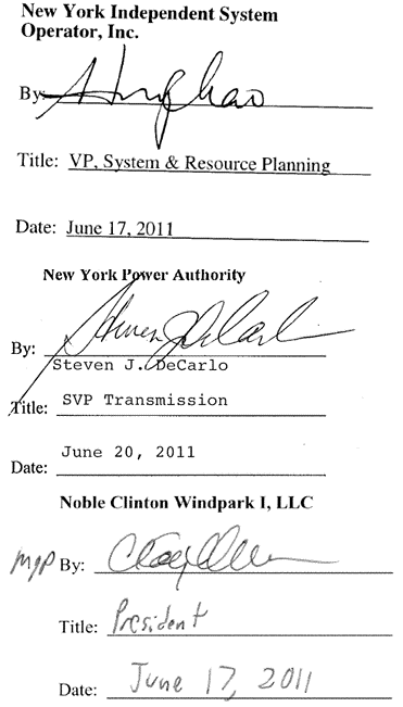
a. In Phase I, the project will be connected as a tap to the Transmission Owner’s 230kV transmission line MWP-2 via one 230kV circuit breaker in series with one of two ring bus breakers for stuck breaker protection (one in each direction) and a tie-line breaker, as shown on the one-line diagram labeled CL-E-IA-01 attached to this Appendix A as Figure 1. The changes to the existing MWP-2 line protection for this arrangement are described in Phase I System Upgrades in Section II of this Appendix A.
b. Civil/Site work: The Developer will provide site civil work including drainage, finish grade and stone the site. Drainage from the switchyard will be promoted by sloping the base layer below the crushed stone at the site with a minimum slope of 0.5 percent to provide adequate drainage and prevent the accumulation of standing water. The switchyard area shall be covered with a 6 inch layer of 0.75 inch crushed stone and will extend for a distance equal to 5 feet beyond the fence line. Disturbed areas which will not receive stone will be mulched and seeded. Site work, grading, fencing and drainage will be mostly completed during Phase I construction, since the foundations and site work associated with Phase II are completed during Phase I construction.
c. Foundations: Foundations will be designed in accordance with generally accepted practices of soil mechanics. Foundation works will be completed during Phase I, including Phase II equipment foundations for the second incoming A-Frame structure and two additional breakers.
d. Grounding: The substation yard is L-shaped with the outer leg dimensions of the ground grid of 338 feet by 507 feet which includes the area 5 feet outside the perimeter fence. Substation grounding grid resistance shall be designed to be less than 5 ohms per IEEE-80, measured without external ground and without the grounding grid of the Large Generating Facility connected. In addition, the 230 kV Control Building shall be furnished with a special high frequency grounding system for the protection of electronic equipment from transient electrical noises as recommended by IEEE 1100.
The below grade grounding system installed in Phase I includes the ground grid and ground wire tails for the Phase II work. The grounding work associated with Phase II is the above grade connections to Phase II equipment.
e. Transmission Line Tap: Transmission Owner has installed an in-line dead end structure in MWP-2 to tap the line into the substation. One line tap will be brought into the substation during Phase I by Developer. The fly taps will consist of one 795 ACSR conductor per phase and a static wire to be installed by Transmission Owner. The static wires will be extended overhead into the substation by Developer. Another ground connection will be made from the substation ground grid to the static wire ground rod at the foot of the two overhead lines before and after the tap by Developer.
f. Station Service: Station service is established from two transformers, each three-phase 225kVA pad is mounted with 34500/19200V primary and 208/120V secondary. One is connected to the 34.5kV side of the Ellenburg 230/34.5kV transformer, another is connected to the Clinton 230/34.5kV transformer. The Clinton 34.5kV/208V transformer is dedicated to the 230 kV Control Building, the other will serve the Developer Attachment Facility Control Building described in Section I.A. of this Appendix A. A single phase, 600 ampere, 120/240 volt service from the local utility will be used as a backup source for the substation station service. This provides separately metered local utility service to the Transmission Owner 230 kV Control Building and the Developer Attachment Facility Control Building described in Section I.A. of this Appendix A.
g. Protective Relaying:
- Primary Line Protection: Distance relaying protection shall be provided via a numerical distance relay. This relaying system shall be set selective within the prescribed zones of protection based on the system protection analysis. The relay will directly trip and block the closure of the breaker(s). The relay shall be of utility grade and meet Transmission Owner’s standards.
- Secondary Line Protection: Distance relaying protection will be provided via a high speed microprocessor based distance relay. This relay shall be set to be selective within the prescribed zones of protection based on system protection analysis. The relay will directly trip and block the closure of the breaker(s). The relay shall be of utility grade and meet Transmission Owner’s standards.
- Breaker Failure: Two independent primary and secondary breaker failure relaying systems provide redundant breaker failure protection. After a circuit breaker trip is initiated the breaker failure relay will begin a countdown timer. If the circuit breaker fails to open within a specified period, then the breaker failure relay will trip its associated lockout relay to trip and block closure of the adjacent and series line circuit breakers. The breaker failure relaying at the Ryan Substation does not send direct transfer trip to the remote terminal substation. The series line breaker is provided to isolate stuck breakers from the 230kV system. The relay shall be of utility grade and meet Transmission Owner’s standards.
- Transfer Trip: During Phase I, the Ryan Substation is connected via a tap to the MWP-2 line. The line will be tripped by MWP-2 line relay and breaker failure operations at Transmission Owner terminals. Breaker failure conditions at Transmission Owner terminals will be programmed to remotely trip the Ryan Substation incoming breaker upon receiving direct transfer trip (DTT) signals from Willis Substation. Two independent communication channels will be provided for the DTT.
- Synch Check Relay: A synch check relay for each breaker will be used to compare voltages across circuit breakers to prevent the substation breakers from closing out of phase. The relay shall be of utility grade and meet Transmission Owner’s standards.
- Remote Control: Transmission Owner will have the ability to remotely open any and all 230 kV circuit breakers and motorized line disconnect switch from Transmission Owner’s control center via SCADA.
h.Supervisory Control and Data Acquisition (SCADA): The SCADA system will provide full functionality of the 230kV portion of the substation to Transmission Owner through a Transmission Owner specified remote terminal unit (RTU). Developer in turn, will be provided with read only information about the 230kV substation through the RTU.
i.Building: A Control Building is provided for the 230kV system. The Control Building is constructed of hardened pre-cast concrete. The Control Building houses the relay, control, and monitoring devices plus all of the support equipment, i.e., station battery systems, AC/DC distribution, HVAC, etc. The primary and secondary protection and controls are each located in separate rooms. The Control Building has been designed with ample space to allow the installation of relays and fault recording equipment required for Phase II.
A 10 by 10 foot concrete pad with 240v/120v power 60 ampere power connection and pre-fabricated lavatory facility shall be provided by Developer near the Control Building.
j.Steel: The 230kV portion of the substation will be a low profile (non-lattice), rigid bus, and air-insulated arrangement with flexible connections to all equipment. Equipment support structures will be designed by working stress method in accordance with AISC (American Institute of Steel Construction) guidelines for specification, engineering, design, and construction.
k.Microwave Radio System: The Microwave Radio System will be constructed as part of the System Upgrade Facilities (SUFs). An interface to the Microwave Radio System installed as SUFs will be installed as part of this Attachment Facility. The SUFs Microwave Radio System must be a functional complete circuit to Transmission Owner’s control center at the St. Lawrence/FDR Power Plant prior to energization of the Phase I Attachment Facilities.
Phase II
Upon completion of Phase II, the Transmission Owner’s Attachment Facilities will only include those facilities between the Point of Interconnection and the Point of Change of Ownership, as depicted on Figure 2 to this Appendix A. The Transmission Owner’s Attachment Facilities include the section of the interconnecting line from the Point of Change of Ownership to the Point of Interconnection, which includes the bus work, associated project meter, potential and current transformers, metering cabinets in the 230 kV Control Building and line disconnect switch.
Section II.C of this Appendix A describes the Phase II configuration, including the ring bus at the Ryan Substation.
2.Cost Estimates
Transmission Owner’s Attachment Facilities and Ring Bus SUF Cost Estimate* |
Ryan Substation | | | |
| | | |
Description | Installation | | |
| Cost | | |
Primary Substation Equipment | $3,250,000 | | |
Protective relays, controls, RTU and SCADA | $960,000 | | |
Revenue Meters | $195,000 | | |
Control Buildings | $195,000 | | |
230 kV Line Tap | $540,000 | | |
Cable Trenches and Conduits | $620,000 | | |
Site work | $600,000 | | |
Foundations | $640,000 | | |
Structural Steel | $450,000 | | |
Lighting, Security | $220,000 | | |
Spare Parts | $280,000 | | |
Microwave Communication Attachment | $160,000 | | |
Sequence of Events Recorder | $140,000 | | |
Digital Fault Recorder | $80,000 | | |
Demolition and protective rework | $220,000 | | |
Land Acquisition | $80,000 | | |
Access Roads, Survey & Site Clearing | $200,000 | | |
Licensing and Permitting | $120,000 | | |
Engineering | $480,000 | | |
Construction Management | $360,000 | | |
Noble Development Cost | $133,000 | | |
Testing and Commissioning | $230,000 | | |
Other Equipment Cost (15% of install man-hours) | $26,000 | | |
Other Engineering, QA/QC, Project Mgt. | $525,000 | | |
Subtotal | $10,704,000 | | |
Contingency 20% | $2,140,800 | | |
Other Indirects 15% | $157,680 | | |
Total Transmission Owner Attachment Facilities and Ring Bus SUF Cost | $13,002,480 | | |
| | | |
*Note that this cost estimate includes the cost estimate for the Ryan Substation Ring Bus System Upgrade Facilities described in Section II.C. of this Appendix A. The cost of the Ryan Substation ring bus System Upgrade Facilities will be shared between the Ellenburg Windfield and the Clinton Windfield projects.
II.SYSTEM UPGRADE FACILITIES
This section identifies the System Upgrade Facilities (“SUFs”) jointly required for the following Class Year 2006 projects: Altona Windfield, Ellenburg Windfield, Clinton Windfield, Marble River Wind Farm and Marble River Wind Farm II. The SUFs required by all of the identified projects will be referred to as the “Common SUFs.” In addition to Common SUFs, other limited SUFs required for the Altona Windfield,[1] Ellenburg Windfield, and the Clinton Windfield are described below.
The SUFs will be constructed in two phases: Phase I and Phase II. The Phase I work will include the Phase I microwave communications SUFs described in Section II.A., below, and the Willis and Plattsburgh Substation upgrades described in the Phase I sections of Section II.B., below.
The Common SUFs include only the following:
- Microwave Communications SUFs
a. Moses (St. Lawrence/FDR Power Plant)
b. Massena Substation
c. Willis Substation
d. Ryan Substation
e. Big Hill
f. Plattsburgh Substation
- Willis and Plattsburgh SUFs, Phase II Only
A.Microwave Communications System Upgrade Facilities
Additions and modifications to the existing Transmission Owner microwave communications system will be made to support the operations of new substations for the Noble Altona (“Duley Substation”), Noble Clinton, Noble Ellenburg (together, “Ryan Substation”) and Marble River (“Patnode Substation”) wind fields.
The system will be comprised of a new digital microwave (backbone) system operating in the 6.7 GHz frequency band with two spur links operating in the 18.7 GHz frequency band. The system will interconnect with the existing Transmission Owner digital microwave system at the Willis Substation on the west and terminating at the existing Plattsburgh Substation on the east. This project will comprise the backbone system.
The backbone system will utilize existing towers at Willis and Plattsburgh substations, and require a new 275 ft tower located in Altona at a site called Big Hill and a new 195 ft tower in the new Ryan Substation. The backbone link runs from Willis to Ryan to Big Hill to Plattsburgh. As part of Developer Attachment Facilities, spur links will run from Ryan Substation to Patnode Substation and from Big Hill to Duley Substation.
The Transmission Owner’s existing analog microwave link between Massena Substation and the St. Lawrence/FDR Moses Dam Site will also be upgraded by adding a digital link to accomplish data communication from Developer’s facilities to Transmission Owner’s operations center at St. Lawrence.
The scope of work at each site will include the following:
Phase I
Willis Substation:
The new communications equipment will be housed in the existing building and the new antenna mounted on the existing tower. The scope of work will include the following:
Grounding: The grounding of the existing substation shall be inspected for adequacy, expanded to cover new installations, and the existing Control Building upgraded accordingly for a high frequency grounding system to safeguard electronic and telecommunication equipment from transient overvoltage as recommended by IEEE 1100 and Motorola grounding and Bonding Manual, R56.
Tower Evaluation: A structural evaluation of the existing tower and foundation for the new equipment has been performed and the tower was confirmed compliant with Transmission Owner’s and ANSI/TIA 222-G-2005 Class III standards. The tower was originally designed for future additions.
Antennas: A 6 foot diameter antenna pointing to Ryan Substation and a working platform will be installed on the existing tower at the 180 ft and 176 ft levels respectively in accordance with the design specifications.
Radio Equipment: Radio and associated equipment will be provided in accordance with Transmission Owner’s standards.
Ryan Substation:
Civil/site work: The microwave tower and equipment shelter will be located within the new substation and no additional site work will be required.
Foundation: Reinforced concrete mat foundation with piers.
Grounding: Tower will be provided with a lightning protection system in accordance with EIA requirements and will be connected to the substation grounding system. Communications shelter will be grounded to the below grade grounding system according to the Motorola Grounding and Bonding Manual, R56.
Station Service: Power will be supplied from the substation service supply. Power to the DC equipment will be through a UPS battery/charger system, which will have a 12 hour capacity.
Tower: 195 ft high free standing galvanized steel lattice tower. Tower to be designed to ANSI/TIA 222-G-2005 Class III standards.
Antennas: A 12 ft diameter antenna pointing to Big Hill will be installed 185 ft above ground. A 6 ft diameter antenna pointing to Willis Substation will be installed 160 ft above ground. Provisions will be made in the design for the installation of a 2 ft diameter antenna to the Patnode Substation in accordance with the design specifications.
Building: The communications equipment will be installed in a 10 ft x 13 ft x 9 ft high pre-cast concrete building. Building will be designed to meet New York State Building Code requirements.
Radio Equipment: Radio and associated equipment will be provided in accordance with Transmission Owner standards.
Massena to Moses:
Also included in this System Upgrade Facilities project is the upgrade of the existing analog microwave link between the Massena Substation and the St. Lawrence/FDR Moses Dam site Communications Room with a new digital link. This upgrade link will utilize existing antennas. The waveguide will be replaced in Massena Substation. Equipment and installation will meet Transmission Owner standards.
Phase II
Big Hill
Civil/site work: The microwave tower will be located off a wind farm access road which will be constructed by Developer. A gravel road will be constructed to the tower site. The tower site and the tower guy wire anchor locations will be cleared, graded level and covered with a 6” layer of crushed stone. Each area will be enclosed with a chain link security fence.
Foundation: Reinforced concrete pier foundation for the tower base and communication shelter and reinforced concrete anchor blocks for the guy wires.
Grounding: Tower and guy wires will be provided with a lightning protection system connected to a below grade grounding system. Fence and communications shelter will be grounded to the below grade grounding system. Lightning protection and grounding systems will be in accordance with EIA and NEC requirements and the Motorola Grounding and Bonding Manual, R56.
Station Service: Power will be supplied from the local utility. A back-up propane fueled emergency generator will be provided. The DC equipment power will be supplied through a UPS battery/charger system, which will have a 12 hour capacity.
Tower: 275 foot high guyed mast. Tower is designed to ANSI/TIA 222-G-2005 Class III and Transmission Owner standards.
Antennas: A 12 ft diameter antenna pointing to Ryan Substation will be installed 265 ft above ground. A 6 ft diameter antenna pointing to Plattsburgh Substation will be installed 250 ft above ground in accordance with the design specifications.
Building: The communications equipment will be installed in a 12 ft x 22 ft x 9 ft high pre-cast concrete building. Building will be designed to meet New York State Building Code requirements.
Radio Equipment: Radio and associated equipment will be provided in accordance with Transmission Owner standards.
Plattsburgh Substation:
The new communications equipment will be housed in the existing building and the new antenna mounted on the existing tower. The scope of work will include the following:
Tower Evaluation: A structural evaluation of the existing tower and foundation for the new equipment has been performed. The tower was confirmed compliant with Transmission Owner’s and ANSI/TIA 222-G-2005 Class III standards.
Antennas: A 6 ft diameter antenna pointing to Big Hill will be installed on the existing tower 150 ft above ground in accordance with the design specifications.
Radio Equipment: Radio and associated equipment will be provided in accordance with Transmission Owner specifications.
B.Willis and Plattsburgh Substation System Upgrade Facilities
The Willis Substation and Plattsburgh Substation SUFs will be constructed as described in this Section II.B. and with respect to the Willis Substation, as shown on drawings 070506-EE-1 and 070506-PL-1 attached to this Appendix A as Figures 3 and 4, respectively.
Phase I
Protection System Changes at Transmission Owner’s Willis Substation for the MWP-2 Line
The existing MWP-2 line primary protection is a permissive overreaching transfer trip (POTT) system with unblock logic, using a numerical relay in conjunction with audio tone equipment over single side band power line carrier channels.
The existing MWP-2 line secondary protection utilizes electromechanical relays to provide backup distance protection.
The primary and secondary protection will not essentially change, however the existing breaker failure protection at Willis will be modified to trip the Ryan Substation line breakers remotely. To accomplish this scheme two Direct Transfer Trips (DTTs) will be required. The first DTT-1/MWP-2 equipment required at Willis will include:
- One FSK PLC Transmitter
- One phase C wave Trap
- One Phase C Coupling Capacitor Voltage Transformer (CCVT)
- One phase C Line Tuner
The second DTT-2/MWP-2 equipment will utilize audiotone equipment over the Ryan/Willis microwave communication link described in the Microwave System description.
Phase II
Willis Substation
The Willis Substation WP-1 and WP-2 tap configurations will be each be converted to breaker and a half configuration. The conversion will require the addition of three circuit breakers, modifications to the existing structures, station connections, line terminations, and protection system.
The existing 230kV 2100 bay will be modified by the addition of a third breaker to create separate terminals for the MW-2 and WRY-2 segments of the existing MWP-2 transmission line. PT’s and CVT’s will be added in conjunction with the line relaying modifications.
A new 2300 bay will be added north of the existing 2200 bay in an area previously designated by Transmission Owner for expansion. The new 2300 bay will include two new 230kV circuit breakers, SF6 type, 2000A continuous circuit, rated 900kV, 63 kA circuit breakers, associated disconnect switches, and line terminal equipment to accommodate the relocated WP-1 transmission line. The WP-1 transmission line will be re-designated WPN-1. New PT’s and CCVT’s will be added in conjunction with the new line and relaying systems will be installed for the WPN-1 line.
The MW-1 line will terminate in the 2200 bay. The existing MWP-1 line primary protection is a blocking carrier scheme using electromechanical relays with ON-OFF carrier equipment. The existing MWP-1 line secondary protection utilizes electromechanical relays to provide backup distance protection. New CCVT’s will be added in the 2200 bay.
The existing Direct Transfer Trip is accomplished via audio tone equipment over single side band power line carrier channels. The existing primary and secondary MWP-1 line protection will remain and be re-designated as MW-1 line protection.
The new equipment will include:
- 230kV Circuit Breakers
- 230kV Disconnect Switches
- Potential Transformers
- Capacitive Voltage Transformers
- Primary Protection Panels
- Secondary Protection Panels
- Communication Racks
- Termination Panels
- Wave Traps and Line Tuners
WRY-2 Line
The primary line relaying will include:
- Pilot Scheme; directional comparison unblocking (DCU) and primary direct transfer trip (DTTP) over power line carrier
- New numerical multifunction relay for phase and ground fault protection
- New FSK PLC equipment for DCU
- Reconfigure existing FSK PLC equipment for DTTP
- New hybrids
- Additional auxiliary devices, test switches, lockout relays, etc.
The secondary line relaying will include:
- Pilot Scheme; current differential with secondary DTT (DTTS) over digital microwave.
- New current differential relay
- New Digital multiplexer and/or fiber optic interface unit
- Additional auxiliary devices, test switches, lockout relays, etc.
WPN-1 Line
The primary line relaying will include:
- Pilot Scheme; directional comparison unblocking (DCU) and primary direct transfer trip (DTTP)over power line carrier
- New numerical multifunction relay for phase and ground fault protection
- New FSK PLC equipment for DCU
- New FSK PLC equipment for DTTP
- New hybrids
- Additional auxiliary devices, test switches, lockout relays, etc.
The secondary line relaying will include:
- Pilot Scheme; current differential with secondary DTT (DTTS) over digital microwave
- New current differential relay
- New Digital multiplexer and/or fiber optic interface unit
- Additional auxiliary devices, test switches, lockout relays, etc.
New 230kV Circuit Breakers
New primary and secondary breaker failure relays and their associated lockout relays and test switches are added for each new breaker.
Various switches associated for breaker control are added for each new breaker.
Plattsburgh Substation
The Plattsburgh Substation WP-1 and WP-2 lines will be re-designated DP-1 and RYP-2 respectively. The existing primary and secondary line relaying systems will be replaced with numerical relay systems as shown below.
The new equipment will include:
- Phase C Line Tuners
- Phase C Wave Trap
- Primary Protection Panels
- Secondary Protection Panels
- Communication Racks
- Termination Panels
DP-1 and RYP-2 Lines
The primary line relaying will include:
- Pilot Scheme; directional comparison unblocking (DCU) and primary direct transfer trip (DTTP) over power line carrier
- New numerical multifunction relay for phase and ground fault protection
- New Digital multiplexer and/or fiber optic interface unit
- Additional auxiliary devices, tests switches, lockout relays, etc.
The secondary line relaying will include:
- Pilot Scheme; current differential with secondary DTT (DTTS) over digital microwave
- New current differential relay
- New Digital multiplexer and/or fiber optic interface unit
- Additional auxiliary devices, test switches, lockout relays, etc.
C.Ryan Substation Ring Bus System Upgrade Facilities
As discussed above in Section I.B. of this Appendix A, the Large Generating Facility will, in its final configuration, connect to the Transmission Owner’s 230 kV line MWP-2 via a ring bus at the Ryan Substation. During the Phase I configuration, the Large Generating Facility will connect to the 230 kV line via a single tap. The final ring bus configuration completed as part of Phase II is described below.
The following is the identification and description of the equipment, engineering, procurement, and construction work required to build the System Upgrade Facilities at the 230kV Ryan Substation. This work essentially converts the Phase I configuration, described in Section I.B. to this Appendix A, to the final ring bus configuration.
Phase I
See Section I.B. of this Appendix A.
Phase II
a.In Phase II, one additional 230kV breaker and associated disconnect switch will be installed to convert the tap configuration into the station ring bus configuration. The Phase I tap configuration line series breaker will be removed and a direct connection will be made from the existing tap point to the station ring bus breakers. A second connection to the WP-2 line will be brought into a new position in the expanded ring, as shown on the one-line diagram labeled CL-E-IA-03 attached to this Appendix A as Figure 2. Upon completion of this Phase II, the Willis – Plattsburgh WP-2 line will be segmented into two new 230kV line segments, Willis-Ryan (WRY-2) and Ryan-Plattsburgh (RYP-2). The line protection for this arrangement must be completed as part of the Phase II System Upgrade Facilities described in Section II of this Appendix A.
b.Civil/Site work: The Developer will complete civil/site work during Phase I as described above.
c.Foundations: The Developer will complete foundation work during Phase I as described above.
d.Grounding: The Developer will complete grounding work during Phase I as described above. The work associated with Phase II is the above grade connections to Phase II equipment.
e.Transmission Line Tap: Transmission Owner installed an in-line dead end structure in WP-2 to tap the line into the substation. During Phase II, a second connection to the WP-2 line will be brought into the substation by Developer. The line will be segmented and looped into and out of the substation by Transmission Owner. The fly taps will consist of one 795 ACSR conductor per phase and a static wire to be installed by Transmission Owner. The static wires will be extended overhead into the substation by Developer. Another ground connection will be made from the substation ground grid to the static wire ground rod at the foot of the two overhead lines before and after the tap by Developer.
f.Station Service: The Developer will install the station service during Phase I as described above. The system is designed with capacity and circuit breakers to supply power to the Phase II equipment requiring such service.
g.Protective Relaying:
h.Fault Recording and Monitoring Equipment: Specified by Transmission Owner and procured by Developer, this equipment will be part of the Phase II installation of this project. This equipment includes a Sequence of Events Recorder cabinet and a Digital Fault Recorder cabinet.
i.Supervisory Control and Data Acquisition (SCADA): The SCADA system work will be expanded to provide full functionality of the 230kV substation including the Phase II equipment. Phase II equipment status will also be wired to the RTU.
j.Building: A Control Building will be completed during Phase I as described above. The Control Building has been designed with ample space to allow the installation of Phase II relays and fault recording equipment. The entrance road will be paved to the Control Building and paved parking area(s) shall be provided. A key access motorized entrance gate and manual man-gate shall be provided.
k.Steel: The 230kV portion of the substation will be low profile (non-lattice), rigid bus, and air-insulated arrangement with flexible connections to all equipment. Equipment support structures will be designed by working stress method in accordance with AISC (American Institute of Steel Construction) guidelines for specification, engineering, design, and construction. The second line tap take off structure will be installed in Phase II. Support steel structures will also be added under Phase II for the new breaker disconnect switches.
D.Cost Estimates
| | | |
System Upgrade Facilities Cost Estimate* | | |
| | | |
| | | |
Description | Installation | | |
| Cost | | |
| | | |
Microwave Communication System | $3,619,260 | | |
Willis Substation | $5,873,200 | | |
Plattsburgh Substation | $2,408,200 | | |
| | | |
| | | |
Total System Upgrade Facilities Cost | $11,900,660** | | |
| | | |
| | | |
*Note that this cost estimate does not include the cost estimate for the Ryan Substation Ring Bus System Upgrade Facilities, which is included in the cost estimate set forth in Section I.B.2. of this Appendix A.
** The Class Year 2006 Facilities Study allocated $250,000 of this total System Upgrade Facilities cost among only the Altona Windfield, Ellenburg Windfield, and Clinton Windfield Large Generating Facilities. The remaining $11,650,660 was allocated equally among Altona Windfield, Ellenburg Windfield, Clinton Windfield, Marble River Wind Farm and Marble River Wind Farm II.
|
System Upgrade Facilities Cost Estimate - Microwave Communication System |
| | | |
| | | |
Description | Installation | | |
| Cost | | |
Willis Tower Evaluation | $10,400 | | |
Willis Communication Equipment | $305,000 | | |
Plattsburgh Tower Evaluation | $10,400 | | |
Plattsburgh Communication Equipment | $305,000 | | |
Clinton 195 ft. Tower | $214,000 | | |
Clinton Communication Equipment | $126,000 | | |
Clinton Building Battery & Accessories | $72,000 | | |
Big Hill 275 ft. Tower | $255,000 | | |
Big Hill Communication Equipment | $250,000 | | |
Big Hill Building, Battery, Gen-Set & Accessories | $170,000 | | |
Massena/STL Microwave System Upgrade | $300,000 | | |
Spare Parts | $68,000 | | |
| | | |
Big Hill Land Acquisition | $65,000 | | |
Big Hill Access Roads, Survey & Site Clearing | $135,000 | | |
Licensing and Permitting | $30,000 | | |
| | | |
Engineering | $120,000 | | |
Construction Management | $140,000 | | |
Noble Development Cost | $60,000 | | |
Testing and Commissioning | $60,000 | | |
Other - Equipment Cost (15% of install man-hours) | $42,000 | | |
Other - Engineering, QA / QC, Project Mgt. | $150,000 | | |
| | | |
Subtotal | $2,887,800 | | |
Contingency 20% | $577,560 | | |
Other Indirects 15% | $153,900 | | |
| | | |
Total Microwave System Upgrade | $3,619,260 | | |
| | | |
| | | |
System Upgrade Facilities Cost Estimate - Willis Substation |
| | | |
Description | Installation | | |
| Cost | | |
230 kV Circuit Breakers | $330,000 | | |
230 kV Disconnects | $100,000 | | |
Six Current Transformers | $48,000 | | |
Six Voltage Transformers | $64,000 | | |
Primary Protection Panels | $150,000 | | |
Secondary Protection Panels | $150,000 | | |
Communication Panels | $56,000 | | |
Control Panels | $120,000 | | |
Installation of Equipment | $700,000 | | |
Install Relay and Control Equipment | $300,000 | | |
Overhead Line Rework | $240,000 | | |
Site work | $40,000 | | |
Rework and rewire existing panels | $160,000 | | |
Structural Steel | $150,000 | | |
Demolition | $40,000 | | |
Foundation | $220,000 | | |
Special Line Protection | $100,000 | | |
Willis 230 kV Bus Connector Upgrade | $30,000 | | |
Wave Trap (2) - Single Phase | $56,000 | | |
Transmitter | $24,000 | | |
Receiver | $24,000 | | |
Materials | $32,000 | | |
Wave Trap Installation w/foundation, steel | $80,000 | | |
Land Acquisition / Site Work | $150,000 | | |
Construction Management | $230,000 | | |
Engineering | $292,000 | | |
Testing and Commissioning | $165,000 | | |
Other - Engineering, QA / QC, Project Mgt. | $500,000 | | |
Other - Equipment Cost (15% of install man-hours) | $110,000 | | |
Subtotal | $4,661,000 | | |
Contingency 20% | $932,200 | | |
Others Indirects 15% | $280,000 | | |
| | | |
Total Willis Station System Upgrades | $5,873,200 | | |
| | | |
System Upgrade Facilities Cost Estimate - Plattsburgh Substation | |
| | | |
| | | |
Description | Installation | | |
| Cost | | |
Primary protection panels | $108,000 | | |
FSK Plc panels | $72,000 | | |
Secondary Panels | $108,000 | | |
Digital Multiplexer | $28,000 | | |
Three current transformers | $24,000 | | |
Digital Multiplexer | $28,000 | | |
Three current transformers | $18,000 | | |
Three voltage transformers | $24,000 | | |
Installation of panels | $100,000 | | |
Conduit, cable and wiring | $200,000 | | |
Rework and rewire existing panels | $60,000 | | |
Other - Relay & Control Installation | $200,000 | | |
Special Line Protection | $100,000 | | |
| | | |
| | | |
Engineering | $220,000 | | |
Construction Management | $105,000 | | |
Noble Development Cost | $100,000 | | |
Other - Equipment Cost (15% of install man-hours) | $36,000 | | |
Testing and Commissioning | $80,000 | | |
Other - Engineering, QA / QC, Project Mgt. | $300,000 | | |
| | | |
Subtotal | $1,911,000 | | |
Contingency 20% | $382,200 | | |
Others Indirects 15% | $115,000 | | |
| | | |
Total Plattsburgh System Upgrades | $2,408,200 | | |
| | | |
| | | |
| | | |
III.ALLOCATION OF SYSTEM UPGRADE FACILITY WORK BETWEEN DEVELOPER AND TRANSMISSION OWNER
The following System Upgrade Facility (“SUF”) work will be performed by Noble Clinton Windpark I, LLC (“Noble Clinton”) and Noble Ellenburg Windpark, LLC (“Noble Ellenburg”), and Transmission Owner in accordance with the System Upgrade Facilities Study – Study Work Agreement Report (revised April 6, 2007) (the “SUF Report”). Noble Clinton and Noble Ellenburg shall be referred to collectively herein as “Clinton and Ellenburg.” The SUFs are set forth in detail in Section II of this Appendix A.
A. Microwave Communications System Upgrade Facilities Scoping
A small portion of the work for the microwave system will be performed by Transmission Owner, and the remainder will be performed by Clinton and Ellenburg.
Clinton and Ellenburg will provide the design, procurement and installation/construction services based on the technical specifications prepared and issued by Transmission Owner, titled “Technical Specifications for the Communications Systems Supporting the North Country Wind Farm Substations” and “Technical Specifications for the Digital Microwave System between the St. Lawrence Power Project and the Massena Substation.” Clinton and Ellenburg will provide all communications, site and facility engineering required, except for engineering relating specifically to the interface to Transmission Owners existing communications circuits and facilities. In addition, Clinton and Ellenburg will complete the land procurement for the tower locations and will prepare and submit all required permit modifications and permit applications for the tower sites, except for the Federal Aviation Administration and Federal Communications Commission applications that have been prepared and submitted by Transmission Owner.
The civil design for the roads and the electrical design for the primary power feed will be designed and installed by Clinton and Ellenburg. The design, procurement and construction of the site access, site improvements, towers, foundations, communications equipment and site facilities at the Ryan and Big Hill sites will be completed by Clinton and Ellenburg. Clinton and Ellenburg will furnish and install the communication equipment at St. Lawrence/Moses, Massena, Willis, Ryan, Big Hill and Plattsburgh. The equipment at Transmission Owner’s Willis, Massena and Plattsburgh Substations and at Transmission Owner’s St. Lawrence/Moses Power Project will be installed under safety and coordination clearances from Transmission Owner (i.e., Transmission Owner’s Clearance and Protection Procedure – Lockout/Tagout Program (“CPP-1”) on existing towers or structures, as applicable.
In coordination with Clinton and Ellenburg and in accordance with Appendix B, Transmission Owner will terminate wiring and participate in the commissioning by Clinton and Ellenburg of the microwave equipment located inside the St. Lawrence/Moses, Massena, Willis and Plattsburgh Substations. Clinton and Ellenburg will furnish and install this equipment for Transmission Owner, so that Transmission Owner can undertake the final wiring terminations and commissioning work as a complete circuit to complete the communications from the Plattsburgh Substation to Big Hill, Ryan Substation, Willis Substation, Massena Substation to Moses. Transmission Owner will develop the communications protocols and data flow over the circuits.
B. Willis Substation System Upgrade Facilities Scoping
Phase I
A small portion of the work for the Phase I modifications to the Willis Substation will be performed by Transmission Owner, and the remainder will be performed by Clinton and Ellenburg. The full scope includes the installation of a wave trap, a CCVT and modifications/additions to relaying on the MWP-2 line.
Clinton and Ellenburg will design and procure the materials based on the outline specifications that were prepared and issued by Transmission Owner. The scope of the Clinton and Ellenburg effort will include both the materials for the exterior installations by Clinton and Ellenburg and interior installation items for Transmission Owner installation inside the Control Building in new communication racks. In addition, Clinton and Ellenburg will be responsible for the exterior and interior construction work and provide construction management services in coordination with Transmission Owner.
The civil design for the foundations and the electrical design for the cable runs into the Control Building will be designed by Clinton and Ellenburg. The equipment has been selected and procured to meet Transmission Owner requirements and where possible, match similar equipment being installed by Clinton and Ellenburg as part of the Ryan and Duley substations. The construction of the foundations, structures, wave traps, CCTV and cable runs into the Control Building at the Willis Substation will be completed by Clinton and Ellenburg. The equipment will be installed by Clinton and Ellenburg under Safety and Clearances procedures from Transmission Owner, using Transmission Owner’s CPP-1. Security background checks will be performed, per Transmission Owner’s procedures, on all personnel working in or on Transmission Owner facilities.
Transmission Owner will terminate and participate in the commissioning by Clinton and Ellenburg of the equipment located inside the Control Building of the Willis Substation. Clinton and Ellenburg will install the equipment so that Transmission Owner can undertake the termination and commissioning work as a complete circuit to complete the tie from the Willis Substation to the new windpark substation. Transmission Owner will develop the communications protocols and data flow over the circuits.
Phase II
A small portion of the work for the Phase II modifications to the Willis Substation will be performed by Transmission Owner, and the remainder will be performed by Clinton and Ellenburg. The detailed scope for Transmission Owner and Clinton and Ellenburg including interface points shall be defined during the detailed engineering phase and, as such documents become available, copies will be delivered by Clinton and Ellenburg to the NYISO, Transmission Owner, Noble Altona Windpark, LLC and Marble River, LLC. The full scope includes the installation of a third two-breaker bay and disconnect switches at the Willis Substation, the 2300 bay (to accommodate a realignment of the tie-in point for the WP-1 Willis to Plattsburgh transmission line) and the addition of a breaker to the 2100 bay for the WP-2 line, all to allow for the lines to be better able to respond to certain contingent operating conditions and faults on the system. Clinton and Ellenburg shall provide detailed information as soon as it is available.
Clinton and Ellenburg will design the upgrades and purchase the materials based on a Transmission Owner approved design. Clinton and Ellenburg will procure both the materials for the exterior and interior installations as well as the items to be used inside the Control Building in new and existing relay panels and communication racks, some of which will be installed by Transmission Owner. In addition, Clinton and Ellenburg will be responsible for the exterior and interior construction work and provide construction management services in coordination with Transmission Owner.
The civil design for the foundations and the electrical design for the cable runs into the termination cabinets in the control building basement will be designed and installed by Clinton and Ellenburg. The equipment will be selected and procured in accordance with the specifications developed during the detailed engineering phase, copies of which shall be furnished to the NYISO, Transmission Owner, Noble Altona Windpark, LLC and Marble River, LLC. The construction of the foundations, structures, breakers, switches, bus work and cable runs into the Control Building to the location of the termination cabinets, including terminations at the yard and termination panel end will be completed by Clinton and Ellenburg. All high voltage 230kV connections to new work and modifications of existing transmission lines will be performed by Transmission Owner. The equipment and work at the Willis Substation will be installed under Transmission Owner’s CPP-1.
Clinton and Ellenburg will furnish and install, and Transmission Owner will terminate and participate in commissioning by Clinton and Ellenburg of the equipment located at the Willis Substation. Transmission Owner will provide Protection & Controls Engineering, terminate the wires to the termination cabinets from the new control panels and new relays in existing control panels, install wiring from the termination cabinets to the control panels and relays, install relays and equipment in the existing panels, and Transmission Owner will commission such work. Transmission Owner will develop the communications protocols and data flow over the circuits.
C. Plattsburgh Substation System Upgrade Facilities Scoping
Phase I
Transmission Owner will design and install the modifications required for the Phase I work at Plattsburgh Substation.
Phase II
A small portion of the work for the Phase II modifications to the Plattsburgh Substation will be performed by Transmission Owner, and the remainder will be performed by Clinton and Ellenburg. A detailed definition of the specific scope for Transmission Owner and Clinton and Ellenburg including interface points shall be defined during the design phase and, as such documents become available, copies will be delivered to the NYISO, Transmission Owner, Noble Altona Windpark, LLC and Marble River, LLC. The full scope includes the installation of wave traps, CCVT’s and modifications and/or additions to relaying on the MWP-1 and MWP-2 lines. These lines will be reconfigured at the completion of Phase II to connect to Duley and Patnode Substations on MWP-1 and the Ryan Substation on MWP-2.
Clinton and Ellenburg will design the upgrades and purchase the materials based on the outline specification that was prepared and issued by Transmission Owner. The work to be performed by Clinton and Ellenburg will include both the materials for the exterior and interior installations and items for Transmission Owner installation inside the control building in existing relay panels and communication racks. In addition, Clinton and Ellenburg will be responsible for the exterior and interior construction work and will provide construction management services in coordination with Transmission Owner.
The civil design for the foundations and the electrical design for the cable runs to the control room will be designed by, as approved by Transmission Owner, and installed under the supervision and control of Clinton and Ellenburg. The equipment will be selected and procured in accordance with the specifications developed during the detailed engineering phase, copies of which shall be furnished to the NYISO, Transmission Owner, Noble Altona Windpark, LLC and Marble River, LLC. The construction of the foundations, structures, wave traps, CCTV and cable runs into the control building to the termination cabinets will be completed by Clinton and Ellenburg. The work at the Plattsburgh Substation will be installed under Transmission Owner’s CPP-1.
Transmission Owner will provide Protection and Controls Engineering, install and terminate wiring from the termination cabinets to the control panels and relays, install relays and equipment in the existing panels, and will commission such work inside the 230kV control building. Transmission Owner will develop the communications protocols and data flow over the circuits.
IV.POWER SYSTEM STABILIZERS PURSUANT TO LGIA SECTION 5.4.
N/A
V.DEVELOPER’S ESTIMATED TAX LIABILITY, LGIA SECTION 5.14.4.
$0.00
- TRIAL AND COMMERCIAL OPERATIONS
The Large Generating Facility may commence Trial Operations and achieve Commercial Operation upon completion of Phase I of the Attachment Facilities and System Upgrade Facilities as described in Sections I and II of this Appendix A.
The Large Generating Facility will be comprised of two separately-queued projects (i.e., a 79.5 MW capacity project at queue position no. 172 (“Clinton I”) and a 21 MW capacity project at queue position no. 211 (“Clinton II”)). The Large Generating Facility, including Clinton II, will commence Commercial Operation before the final settlement of the Class Year 2007 Facilities Study that includes Clinton II. The Developer shall accept the cost allocation for any System Upgrade Facilities for Clinton II from the Class Year 2007 Facilities Study and shall post any
Security as required pursuant to Attachment S of the NYISO OATT. The Developer shall also make any Headroom payments required by the Class Year 2007 Facilities Study pursuant to Attachment S. If the Attachment Facilities or System Upgrade Facilities for Clinton II identified in the Class Year 2007 Facilities Study differ in any material way from the Attachment Facilities and System Upgrade Facilities identified in this Agreement, the Parties shall amend this Agreement, pursuant to its sections 29.11 and 29.12, to reflect the Attachment Facilities and System Upgrade Facilities identified in the Class Year 2007 Facilities Study.
VII.TRANSFER OF PROPERTY
Upon completion of construction, testing and acceptance of the Big Hill site by Transmission Owner, Developer will convey the fee interest of the property (depicted in DHL Survey Map Drawing No. 07034, attached to this Appendix A as Figure 5) to Transmission Owner by warranty deed and will transfer to Transmission Owner title to the facilities constructed thereon, free and clear of any liens or encumbrances. A permanent 30 foot wide easement for Transmission Owner to access, operate and maintain the Big Hill facility will be provided by Developer.
Upon completion of construction, testing and acceptance of the Ryan Substation (Phase I and Phase II), Developer will convey the fee interest of the property (depicted in Survey Map No. 07-1135, attached to this Appendix A as Figure 6) to Transmission Owner by warranty deed and will transfer to Transmission Owner title to the Transmission Owner’s Attachment Facilities and System Upgrade Facilities (including the ring bus SUF) constructed thereon, free and clear of any liens or encumbrances.
VIII.OPERATIONS AND MAINTENANCE
Pursuant to Section 10.5 of this Agreement, Developer shall pay the reasonable expenses (including overheads) for the operation, maintenance, repair and replacement of Transmission Owner’s Attachment Facilities and incremental operating and maintenance expenses incurred in association with System Upgrade Facilities, if and to the extent provided for under Attachment S. For Transmission Owner’s Attachment Facilities, such expenses are calculated as follows:
a.Contractor expenses for labor, equipment and materials. These expenses shall be invoiced as the actual amount of the Contractors’ invoices, plus, Transmission Owner shall also be entitled to a fee of 5 % of such amount(s).
b.Transmission Owner’s labor, craft and salaried personnel directly working on the operation, maintenance or repair of the Transmission Owner Attachment Facilities. These expenses shall be invoiced on the basis of Transmission Owner’s standard labor rate times the number of hours worked (including adjustment for overtime hours, if applicable). Such standard rate is subject to change in accordance with Transmission Owner’s normal budgeting practices.
c.Equipment and materials purchased by the Transmission Owner (other than those covered under subsection (a), above). These expenses shall be invoiced on the basis of the actual cost of such material. Transmission Owner shall also be entitled to a fee of 15% of such amount(s).
d.Use of vehicles and construction equipment. These expenses shall be invoiced at Transmission Owner’s cost. Transmission Owner shall also be entitled to a fee of 10% of such amount(s).
e.Miscellaneous expenses (e.g. local utility charges for power; local telephone/communication fees; other fees such as FAA licenses). These expenses shall be invoiced at Transmission Owner’s cost. Transmission Owner shall also be entitled to a fee of 5% of such amount(s).
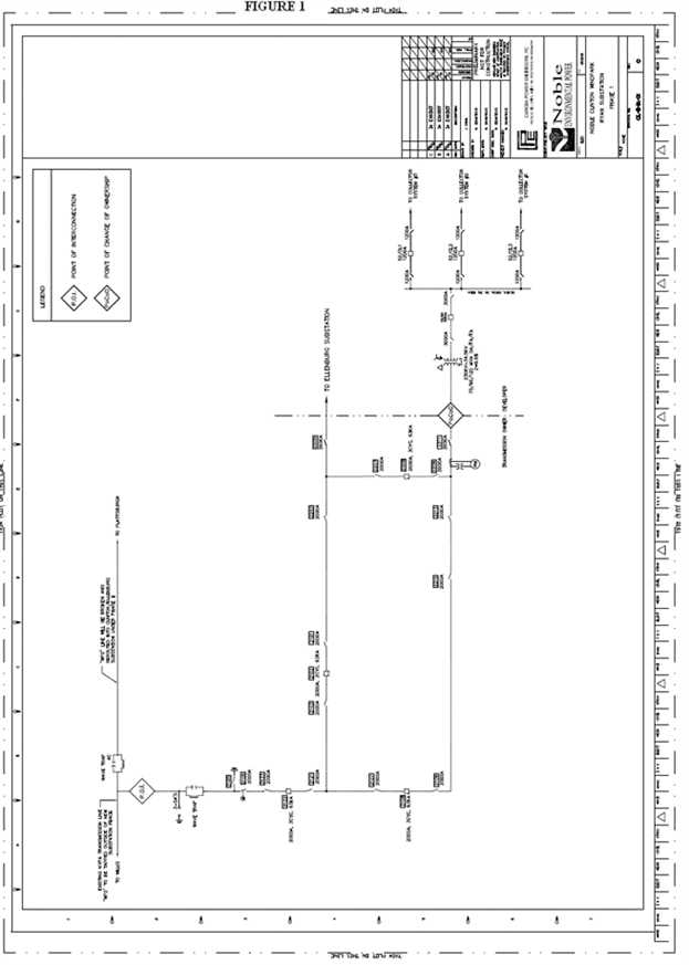
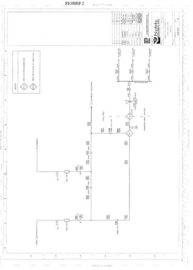

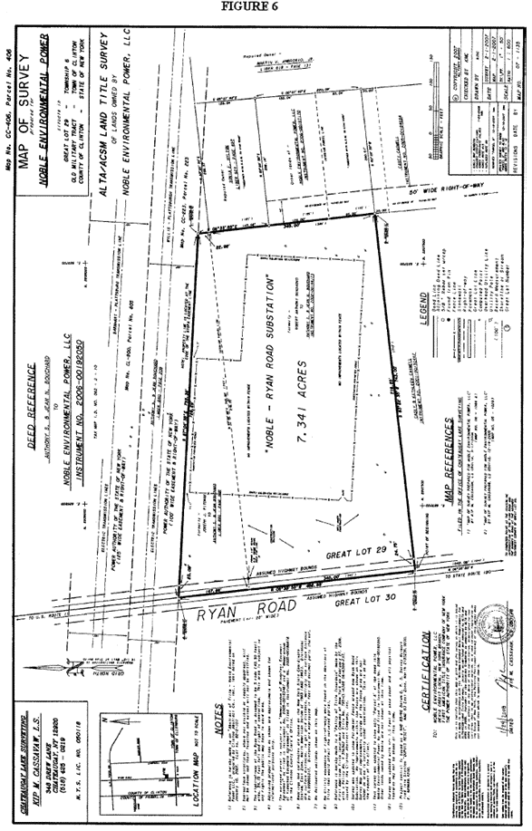
Effective Date: 6/20/2011 - Docket #: ER11-4004-000 - Page 1
NYISO Agreements --> NYISO Service Agreements --> LGIA Among NYISO, NYPA and Noble Clinton Windpark
Appendix B
Milestones
I.Selected Option pursuant to Article 5.1
The selected option under Article 5.1 of this Interconnection Agreement is the “Option to Build” except for Transmission Owner’s engineering, procurement and construction obligations which shall be performed in accordance with the “Standard Option.” The Parties have agreed to the division of responsibility and scope as described in Section III of Appendix A.
II. MilestoneS
| RESPONSIBLE | START | MILESTONE |
Phase I | | | |
Dev. provide security to Transmission Owner (“TO”) per Article 11.5 | Dev. | | 12 Jul 2007 |
| | | |
Willis Substation | | | |
- Engineering / Procurement Completed
| Dev. | | 2 Apr 2007A |
- Dev. Mobilizes and Starts
| Dev. | | 5 Nov 2007A |
- Dev. completes WP-2 installation
| Dev. | | 21 Nov 2007A |
- Dev. deliver Trn Ovr Package for WP-2
| Dev. | | 19 Nov 2007A |
- TO Review of Trn Ovr Package
| TO | 19 Nov 2007A | 28 Nov 2007A |
- Line outage WP-2 NYPA H Connections
| | 28 Nov 2007A | 30 Nov 2007A |
- Ready for Ryan (PLC communications only)
| TO | | 26 Jan 2008 |
| | | |
Ryan Substation | | | |
- Engineering & Procurement Completed
| Dev. | | 5 July 2007A |
| Dev. | | 1 May 2007A |
- Dev. Installation Complete
| Dev. | | 23 Jan 2008 |
| | 29 Nov 2007A | 30 Nov 2007A |
- Dev deliver final Trn Ovr Package
| Dev. | 22 Feb 2008 | |
- TO review of Trn Ovr Package (delivered in progress)
| TO | 22 Feb 2008 | 7 Mar 2008 |
- TO Concurrent activities (post-Dev. delivery of Trn Ovr Package)
| | | |
| TO | 15 Dec 2007A | 12 Jan 2008A |
| TO | 16 Jan 2008 | 19 Feb 2008 |
- Operations and P+C Final Walk Through
| TO | 4 Feb 2008 | 22 Feb 2008 |
| | | |
Ryan Microwave Communications | | | |
| Dev. | | 27 Aug 2007A |
- Dev. completes MW installation
| Dev. | | 15 Jan 2008A |
- Dev. deliver Trn Ovr Package for MW
| Dev. | | 13 Feb 2008 |
- TO Review of Trn Ovr Package
| TO | 14 Feb 2008 | 27 Feb 2008 |
- Ready for Ryan Tap–Ryan MW Communications
| | | 22 Feb 2008 |
| | | |
Willis Microwave Link (to Ryan) | | | |
| Dev. | | 14 Sep 2007A |
- Contractor Mobilizes on Site
| Dev. | | 27 Dec 2007A |
- Dev. Trn Ovr Package delivered to TO
| Dev. | | 12 Feb 2008 |
- TO Review of Trn Ovr Package
| TO | 13 Feb 2008 | 26 Feb 2008 |
| Dev. | 4 Jan 2008 | 9 Jan 2008A |
- New circuit terminations (final plug-ins only)
| TO | | 19 Feb 2008A |
| | | 26 Feb 2008 |
| | | |
Massena Microwave Link (to Moses) | | | |
| TO | 10 Jun 2007A | 23 Jun 2007A |
| Dev. | 3 Jan 2008 | 8 Jan 2008A |
- Dev. Trn Ovr Package delivered to TO
| Dev. | | 8 Feb 2008 |
- TO review of Trn Ovr Package
| TO | 9 Feb 2008 | 22 Feb 2008 |
- Conduct TO Approved Acceptance Testing
| Dev. | | 26 Feb 2008 |
| Dev. | 22 Jan 2008 | 27 Jan 2008A |
| | | 26 Feb 2008 |
| | | |
Moses Microwave Link (to Massena) | | | |
| TO | 10 Jun 2007A | 23 Jun 2007A |
| Dev. | 4 Jan 2008 | 8 Jan 2008A |
- Dev. Trn Ovr Package delivered to TO
| Dev. | | 11 Feb 2008 |
- TO review of Trn Ovr Package
| TO | 12 Feb 2008 | 25 Feb 2008 |
- Conduct TO Approved Acceptance Testing
| Dev. | | 26 Feb 2008 |
| Dev. | 21 Jan 2008 | 27 Jan 2008A |
| | | 26 Feb 2008 |
| | | |
Microwave Communications – Backbone: M/MS/W/Ryan (Summary item) | | | |
- Acceptance testing M/MS/W/RY
| TO/Dev. | 25 Jan 2008 | 26 Feb 2008 |
- Termination communication circuits (final plug-ins) M/MS/W
| TO | | 19 Feb 2008A |
- MW backbone ready (M/MS/W/RY) for Ryan energization
| | | 26 Feb 2008 |
In Service Date | Dev./TO witness | | 7 Mar 2008 |
Initial Synchronization Date | Dev. | | 12 Mar 2008 |
Commercial Operation Date | Dev. | | 20 Mar 2008 |
| RESPONSIBLE | START | FINISH |
Phase II | | | |
| | | |
Big Hill Microwave Communication | | | |
- Physical Engineering Completed
| Dev. | | 15 Aug 2007A |
- Installation/commissioning Complete
| Dev. | | 15 May 2008 |
- Dev. Trn Ovr Package delivered to TO
| Dev. | | 17 May 2008 |
- TO review of Trn Ovr Package
| TO | 17 May 2008 | 31 May 2008 |
| | 19 May 2008 | 27 May 2008 |
| | | 2 Jun 2008 |
| | | |
Plattsburgh Microwave Upgrade | | | |
- Physical Engineering Completed
| Dev. | | 21 Feb 2008 |
- Installation/commissioning complete
| Dev. | | 28 Mar 2008 |
- Dev. Trn Ovr Package delivered to TO
| Dev. | | 30 Mar 2008 |
- TO review of Trn Ovr Package
| TO | 30 Mar 2008 | 15 Apr 2008 |
| | 30 Mar 2008 | 7 Apr 2008 |
| | | 10 Apr 2008 |
| | | |
Willis Substation | | | |
| Dev. | | 28 Feb 2008 |
| Dev. | | 14 Apr 2008 |
| | | |
Bay 2100 (WP-2) | | | |
- Relays delivered, Relay Panels installed
| Dev. | 5 Mar 2008 | 19 Apr 2008 |
- 2100 Outage (drop/cut/tap)
| TO | 3 Mar 2008 | 7 Mar 2008 |
| Dev | 29 Apr 2008 | 1 May 2008 |
- TO wiring / testing of relay panels
| TO | 22 Apr 2008 | 27 May 2008 |
| Dev | | 2 Jun 2008 |
- Dev. deliver Trn Ovr Package
| Dev. | | 11 Jun 2008 |
- TO Trn Ovr Package Review
| TO | 11 Jun 2008 | 22 Jun 2008 |
| TO | 3 Jun 2008 | 5 Jul 2008 |
- 2100 Outage M/W/P Center Bkr connection
| Dev./TO | 15 Sep 2008 | 21 Sep 2008 |
| | | |
Bay 2300 (WP-1) | | | |
- Bay 2300 Construction Completed
| Dev. | | 30 May 2008 |
- Dev. deliver Trn Ovr Package
| Dev. | | 3 Jun 2008 |
- TO Trn Ovr Package Review
| TO | 3 Jun 2008 | 28 Jun 2008 |
| Dev. | 3 Jun 2008 | 24 Jun 2008 |
- Dev. Completes Functional Items* on Punchlist
| Dev. | 17 Jun 2008 | 28 Jul 2008 |
- Outage 2300 Bay to 2BW (West Bus)
| TO | 16 Aug 2008 | 17 Aug 2008 |
- Outage 2300 Bay to 2BE (East Bus)
| TO | 23 Aug 2008 | 24 Aug 2008 |
- TO Energized Testing of Bay 2300
| TO | 18 Aug 2008 | 19 Sep 2008 |
- Bay 2200/2300 outage – Cut over and segment line WP-1
| TO | 22 Sep 2008 | 26 Sep 2008 |
Plattsburgh | | | |
| Dev. | | 18 Jan 2008A |
- Procurement Completed – Long lead
| Dev. | | 24 Apr 2008 |
- TO approved Design Completed
| TO | | 27 Nov 2007A |
- Dev. Completes WP-1,WP-2 installation of P&C
| Dev. | 9 Apr 2008 | 29 Apr 2008 |
- TO review of Trn Ovr Package
| TO | 6 May 2008 | 15 May 2008 |
| TO | 6 May 2008 | 19 May 2008 |
- Dev. Completes Functional Items* on Punchlist
| Dev. | 15 May 2008 | 15 Jun 2008 |
| | | |
Ryan | | | |
| Dev. | | 15 Apr 2008 |
| Dev. | | 16 May 2008 |
| Dev. | | 8 Aug 2008 |
- Dev. deliver Trn Ovr Package
| Dev. | | 11 Aug 2008 |
- TO review of Trn Ovr package
| TO | 11 Aug 2008 | 22 Aug 2008 |
| Dev. | 11 Aug 2008 | 30 Aug 2008 |
- TO Operations, P&C Final Walkthrough
| TO | 30 Aug 2008 | 14 Sep 2008 |
- Willis / Ryan line segmentation (Predecessors: Big Hill/Platts MW and Plattsburgh Phase II complete)
| TO | 15 Sep 2008 | 21 Sep 2008 |
*The term “Functional Items” refers to all work comprising the relevant scope, including all materials and components, but excluding minor or non-functional punchlist items (i.e., the list of items of Work remaining to be completed which are generally cosmetic in nature and/or not required for the safe and lawful operation of the Facility), have been installed, erected, aligned, and adjusted at the site in a non-operating condition, substantially in accordance with the technical specifications and as acceptable to Transmission Owner.
The following notes apply to all work performed on SUFs and TO Attachment Facilities:
- Developer shall submit to Transmission Owner copies of all required permits including all supporting documentation such as calculations, applications and drawings within 5 business of the execution of this Interconnection Agreement.
B.Transmission Owner work durations do not include holiday work; if a holiday is in the calendar during an event, then extend day-for-day.
C. All Transmission Owner outage durations based upon good weather – inclement weather will extend outages.
D. Transmission System emergencies take precedence over all work and could significantly impact the schedule and durations.
E. Transmission Owner schedules its resources months in advance, and its ability to reschedule manpower is limited by resource allocation to other Transmission Owner projects and tasks. Missing a scheduled Milestone may result in some delay before Transmission Owner can reschedule its manpower to work on the assigned task.
F. Developer will work diligently with Transmission Owner to reconfigure the Ryan Substation “tap configuration” to a “ring bus” by September 21, 2008. Transmission Owner has advised Developer that in order to assure system reliability, the Common SUFs must be completed and ready for operational use as determined by the Transmission Owner (which may occur prior to NYPA’s formal acceptance of the Common SUFs) before Transmission Owner will connect Developer’s Duley Substation or any other Developer connections to Transmission Owner’s WP-1 and WP-2 transmission lines.
G.The turnover package (“Trn Ovr Package”) consists of the following documentation: Punchlist, Record Drawings, all equipment, QA/QC, installation, commissioning, Engineer of Record Professional Engineer certification, color markup of design drawings, warranties.
H. Developer understands and agrees that in parallel to Bay 2100 completion, the Ryan Substation ring bus must be completed. Developer’s obligation to reconfigure the Ryan Substation tap configuration to a ring bus is a material obligation of this Interconnection Agreement.
I.Developer will be responsible for all fines and penalties imposed on Transmission Owner by a Governmental Authority or Applicable Reliability Councils due to any Developer action or inaction relating to the Attachment Facilities or SUFs.
III. TRIGGER DATES FOR COMMON SUFS
The Common SUFs will be installed in accordance with the Trigger Dates for completion of the Common SUFs, set forth on Schedule A to this Appendix B, attached hereto, and consistent with the Milestone Schedule set forth in Section II of this Appendix B. Under certain circumstances described below, if Developer is unable to meet a Trigger Date, the Transmission Owner and NYISO may require Developer to cease all existing efforts to construct or develop the Common SUFs and to transfer any such rights to Transmission Owner or Transmission Owner’s designee.
Notwithstanding the foregoing, it is understood and agreed that an occurrence of an “Uncontrollable Timing Event” shall excuse Developer’s obligation to meet affected Trigger Dates until applicable replacement Trigger Dates have been agreed upon pursuant to Section III(b)(i) below. An “Uncontrollable Timing Event” shall mean an event that causes delays in meeting the Trigger Date(s) as a result of (a) an event of Force Majeure and/or (b) actions by the Transmission Owner, NYISO, NPCC, federal governmental authorities and/or state governmental authorities, and where: (x) such event(s) are beyond Developer’s control; (y) alter(s) Developer’s scope of work as set forth in Appendix A; and (z) there would not have been a delay that causes Developer to be unable to meet the Trigger Date(s) but for such event(s). Nothing herein shall: (i) alter or abrogate Parties’ excuse from performance for events of Force Majeure (as defined in this Interconnection Agreement); or (ii) impose any increased obligation, liability or responsibility on Transmission Owner or the NYISO to perform its obligations pursuant to this Interconnection Agreement.
Except to the extent discussed above, Developer and Transmission Owner agree that neither the Milestone Schedule set forth in Section II of this Appendix B, nor the Trigger Date Schedule set forth on Schedule A to this Appendix B shall be modified in any way that will change or will likely change a Trigger Date without the prior written consent of Noble Altona Windpark, LLC (“Altona”) and Marble River, LLC (“Marble River”) (as applicable).
(a) If Developer determines it will be unable to meet one or more Trigger Date(s), Developer shall notify Transmission Owner, NYISO, Ellenburg, Altona and Marble River in writing within five (5) Business Days of such determination. In its notice, Developer shall specify (i) whether it is claiming that its inability to meet any such Trigger Date(s) is/are attributable to Uncontrollable Timing Event(s), (ii) the reasons supporting such claim and, if known, the anticipated date the Uncontrollable Timing Event(s) will end, and (iii) its revised timeframe for meeting the Trigger Date(s).
(b) Transmission Owner and NYISO shall promptly review Developer’s notice and promptly notify Ellenburg, Altona and Marble River of Transmission Owner’s and NYISO’s determination.
(i) If Transmission Owner and NYISO jointly have a reasonable basis for determining, and in fact determine, that Developer’s failure to meet the Trigger Date(s) is due to an Uncontrollable Timing Event(s), then (A) Developer shall be relieved of its obligation to meet the Trigger Date(s) in question until the Uncontrollable Timing Event ends, and (B) Developer, Transmission Owner, NYISO, Marble River and Altona shall cooperate in good faith to negotiate reasonable replacement Trigger Date(s).
(ii) If Transmission Owner and NYISO jointly have a reasonable basis for determining, and in fact determine, that Developer’s failure to meet the Trigger Date(s) is not due to an Uncontrollable Timing Event, then Developer shall be given a right to cure its failure to meet the Trigger Date within twenty (20) calendar days after receipt of Transmission Owner’s and NYISO’s determination.
(c) If, absent notification from Developer pursuant to Section III(a) above, NYISO and/or Transmission Owner reasonably believe that Developer will be unable to, or has failed to, meet a Trigger Date, NYISO and Transmission Owner shall notify Developer in writing with copies to Ellenburg, Altona and Marble River, requesting Developer to provide responses to the following: (i) whether or not Developer believes it will be unable to or has failed to meet any such Trigger Date; (ii) whether Developer believes any inability to meet a Trigger Date is attributable to an Uncontrollable Timing Event(s); (iii) the reasons supporting any such claim and the anticipated date the Uncontrollable Timing Event will end; and (iv) its estimate for completing the task associated with the missed Trigger Date(s). Within (5) Business Days after Developer’s receipt of the NYISO and/or Transmission Owner notice in this Section III(c), Developer shall respond in writing to NYISO, Transmission Owner, Ellenburg, Altona and Marble River. NYISO and Transmission Owner shall promptly review Developer’s response. The provisions of Section III(b) above shall apply following such review.
(d) If Developer does not meet a Trigger Date for any reason other than the occurrence of an Uncontrollable Timing Event, and has failed to cure such failure of performance within the period set forth in Section III(b)(ii) above, then Transmission Owner and NYISO have the right (but not the obligation) to demand that Developer cease all existing efforts to construct or develop the Common SUFs, and to transfer any such rights to Transmission Owner or Transmission Owner’s designee (which may include Marble River). (Transmission Owner’s designee shall be the “Transferee”). A decision regarding such demand will take into account Marble River’s scheduled in-service date (which shall be no earlier than October 1, 2008), among other considerations. As part of any transfer to Transmission Owner or Transferee, Transmission Owner and NYISO may demand that Developer transfer or convey to the Transmission Owner or Transferee (as applicable) title to, possession of and control of any and all equipment and services procured for the purpose of constructing the Common SUFs, and Developer shall immediately transfer such equipment and services free and clear of any liens or other encumbrances to the Transmission Owner or Transferee (as applicable) accordingly. The terms and conditions with respect to the transfer of such equipment and services shall be customary for transactions of this type in the electric power industry, as reasonably determined by Developer and Transmission Owner jointly.
IV.COST ALLOCATION
Developer will be fully responsible for costs in excess of $11.65 million incurred to complete the Common SUFs, except to the extent that the excess cost is incurred as a result of an “Uncontrollable Cost Event.” An “Uncontrollable Cost Event” shall mean an event that causes costs increases as a result of (i) an event of Force Majeure, (ii) the implementation of the results of the special protection scheme study being conducted as referenced in Appendix 4 (NYPA Phase 2 Protection Design Criteria Document), Paragraph 3.9 of the SUF Report (as such term is defined in Appendix A of this LGIA), (iii) additional channels on the Transwave Communications Systems for the Willis to Plattsburgh circuit requested by NYPA (as described in the August 8, 2007, letter from Noble Constructors, LLC to Marble River as Change Order 1 with a cost impact of $210,954.00), (iv) after transfer pursuant to Section III(d) above, negligence or willful misconduct on the part of the Transmission Owner or Transferee, as applicable, and/or (v) after transfer pursuant to Section III(d), failure of the Transmission Owner or Transferee, as applicable, to take steps reasonably necessary to complete the Common SUFs in a timely manner.
In the event that excess cost is incurred to complete the Common SUFs as a result of an Uncontrollable Cost Event as set forth in subsections (i), (ii) or (iii) above, then such costs will be allocated among the Developer, Ellenburg, Altona and Marble River pursuant to the allocation percentages determined pursuant to Attachment S of the NYISO OATT, and in no event shall such excess costs be the responsibility of Transmission Owner.
In the event that excess cost is incurred to complete the Common SUFs as a result of an Uncontrollable Cost Event as set forth in subsections (iv) or (v) above, then: (A) to the extent that Transmission Owner is responsible for such costs pursuant to the procedures set forth in Attachment S of the NYISO OATT, as such responsibility is determined in accordance with the next paragraph, such costs will be allocated to Transmission Owner; (B) to the extent that Transmission Owner is not responsible for such costs pursuant to the procedures set forth in Attachment S of the NYISO OATT and Marble River is the Transferee, such costs will be allocated among the Developer, Ellenburg, Altona and Marble River pursuant to the allocation percentages determined pursuant to Attachment S of the NYISO OATT; and (C) to the extent that Transmission Owner is not responsible for such costs pursuant to the procedures set forth in Attachment S of the NYISO OATT and neither Transmission Owner nor Marble River is the Transferee, such costs will be allocated equally among the Developer, Ellenburg and Altona.
The Parties agree that in determining the extent of Transmission Owner’s responsibility (if any) for costs pursuant to the procedures set forth in Attachment S of the NYISO OATT, only the Transmission Owner’s actions (or inaction) shall be considered; Transmission Owner shall not be responsible for the actions (or inaction) of any Transferee.
Effective Date: 6/20/2011 - Docket #: ER11-4004-000 - Page 1