


January 31, 2017
Honorable Kimberly D. Bose Secretary
Federal Energy Regulatory Commission 888 First Street, N.E., Room 1A
Washington, D.C. 20426
Re: New York Independent System Operator, Inc. and PJM Interconnection, L.L.C.,
Docket No. ER17-___-000;
Proposed Revisions to Joint Operating Agreement Addressing Interchange
Scheduling and Market-to-Market Coordination on the ABC Interface and JK Interface After the 1,000 MW Wheel Concludes
Dear Ms. Bose:
Pursuant to Section 205 of the Federal Power Act,1 the New York Independent System
Operator, Inc., (“NYISO”) and PJM Interconnection, L.L.C. (“PJM”) (collectively the “RTOs”)
submit, in electronic format, proposed revisions to the Joint Operating Agreement (“JOA”)
between NYISO and PJM that is set forth in Attachment CC (Section 35) to the NYISO’s Open
Access Transmission Tariff (“NYISO OATT”).2 In addition, the NYISO submits proposed
revisions to one section of its Market Administration and Control Area Services Tariff (“NYISO
Services Tariff”). The revisions proposed in this filing primarily address interchange scheduling
and the implementation of Market-to-Market (“M2M”) coordination at the ABC Interface and JK
Interface on the border of Southeastern New York and Northern New Jersey. These interfaces
are currently utilized to wheel 1,000 MW of power from New York to New Jersey over the JK
Interface and from New Jersey into New York City over the ABC Interface. However, this
unique arrangement (referred to as the “1,000 MW Wheel”) will terminate on April 30, 2017.
Accordingly, the RTOs propose to more fully incorporate the facilities that have been used to
effectuate the 1,000 MW Wheel into their interchange scheduling and M2M practices. Without
1 16 U.S.C. §824d.
2 Order No. 714, Electronic Tariff Filings, ¶ 31,276 (2008), and Section 35.1 of the Commission’s regulations, 18 C.F.R. § 35.1(a), allow multiple public utilities that are parties to the same tariff (e.g., a joint tariff such as the JOA) to designate one of the public utilities as the designated filer of the joint tariff. The designated filer submits a single tariff filing for inclusion in its database that reflects the joint tariff, along with the requisite certificates of
concurrence from the other parties to the joint tariff. NYISO is the designated filing party for the JOA. Therefore, NYISO is submitting the JOA modifications in the instant filing along with PJM’s Certificate of Concurrence. The designation of the NYISO as the designated filer for the JOA is for administrative convenience and in no way shall limit PJM’s filing rights under the Federal Power Act as they relate to the JOA.
Honorable Kimberly D. Bose January 31, 2017
Page 2
these proposed revisions, the RTOs will have no tariff provisions governing the operation of the ABC Interface and JK Interface facilities.
I.Background
A. History of the 1,000 MW Wheel
The NYISO and PJM currently implement an Operating Protocol3 to facilitate the
planning, operation, control, and scheduling of energy between the NYISO and PJM associated with two Long-term Firm Point-to-Point Transmission Service Agreements (“2008 TSAs”) entered into by Consolidated Edison Company of New York (“Con Edison”) and PJM, dated April 18, 2008.4 The 2008 TSAs5 were executed in connection with the rollover of two
grandfathered contracts dated May 22, 1975 (as amended May 9, 1978) and May 8, 1978
between Con Edison and Public Service Electric and Gas Company (“PSEG”).
On April 22, 2008, PJM filed the 2008 TSAs along with Operating Protocol in Docket
No. ER08-858-000,6 and on April 23, 2008, NYISO filed the Operating Protocol for
informational purposes in Docket No. ER08-867-000.7 Various parties filed protests and
comments in these proceedings, objecting to the non-conforming provisions of the 2008 TSAs
and the Operating Protocol. The Commission accepted and suspended, subject to refund, the
2008 TSAs and Operating Protocol, consolidated the two dockets and set them for hearing and
settlement procedures.8 After extensive negotiations, the parties filed a settlement agreement on February 23, 2009.9 The Commission approved the settlement agreement, and found the
settlement agreement and the 2008 TSAs and Operating Protocol (revised by the settlement) just and reasonable, on September 16, 2010.10
The two 2008 TSAs, based on the rollover of the grandfathered contracts, currently
provide for Con Edison to deliver 1,000 MW of power to PJM in northern New Jersey, over the
3 See Schedule C to the JOA (NYISO OATT Section 35.22).
4 While the 2008 TSAs were dated and filed in 2008, they became effective on May 1, 2012.
5 The 2008 TSAs consist of a firm point-to-point service agreement for 400 MW designated as Original Service Agreement No. 1874 and a firm point-to-point service agreement for 600 MW designated as Original Service Agreement No. 1873.
6 Submission of PJM Interconnection, L.L.C., Docket No. ER08-858-000 (April 22, 2008).
7 Submission of NYISO, for Informational Purposes, of a New Schedule C to the Joint Operating Agreement Among and Between New York Independent System Operator, Inc. and PJM Interconnection, L.L.C., Docket No. ER08-
867-000 (April 23, 2008).
8 PJM Interconnection, L.L.C., 124 FERC ¶ 61,184, at P 1 (2008).
9Settlement and Offer of Settlement, Docket Nos. ER08-858-000, ER08-867-000 and EL02-23-000 (Feb. 23, 2009). The Settling Parties were PJM, the NYISO, Con Edison, PSEG, PSEG Energy Resources & Trade LLC and the New Jersey Board of Public Utilities.
10 PJM Interconnection, L.L.C. v. Pub. Serv. Elec. & Gas Co., 132 FERC ¶ 61,221, at P 1 (2010), order on reh’g, 135 FERC ¶ 61,018 (2011), aff’d, NRG Power Mktg., LLC v. FERC, 718 F.3d 947 (D.C. Cir. 2013).
Honorable Kimberly D. Bose January 31, 2017
Page 3
JK Interface,11 and for PJM to redeliver the same amount of power to Con Edison in New York City, over the ABC Interface,12 i.e., the 1,000 MW Wheel.13 The terms of the 2008 TSAs are from May 1, 2012 to April 30, 2017. On April 28, 2016, Con Edison informed PJM that it was choosing not to exercise its rollover rights pursuant to sections 2.2 and 2.3 of the PJM Open
Access Transmission Tariff and, therefore, the 2008 TSAs would terminate by their own terms on April 30, 2017.14 Thus, the 1,000 MW Wheel arrangement will come to an end and the
Operating Protocols will become obsolete.
B. Current Interchange Scheduling Process
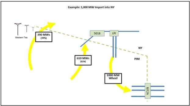
With the 1,000 MW Wheel in place, the NYISO and PJM currently implement
interchange between NYISO and PJM by reviewing offers and scheduling transactions over the
PJM-NY AC Proxy Bus. The scheduled interchange between NYISO and PJM is expected to
flow according to the pre-set distribution of 61% over the PAR-controlled 5018 line (also
referred to as the Ramapo Interface)15 and 39% over the Western ties (which are geographically
located on New York’s border with Pennsylvania). This distribution is explicitly modeled in the
NYISO’s Day-Ahead Market and Real-Time Market. The NYISO’s market models assume that
for every MW of total interchange injected at the proxy bus in the Day-Ahead Market, and for
every MW of incremental change in interchange injected at the Proxy Bus in the Real-Time
Market, 0.61 MW is directed over the 5018 line, and the remainder is directed to flow over the
Western ties. There are some limited circumstances where scheduled interchange may occur
over the ABC Interface and JK Interface when the 5018 line is at its capacity.16
II.Discussion
A. Overview
The RTOs have worked together to develop a revised set of JOA rules to schedule
interchange and implement market-to-market coordination on the ABC Interface and JK
Interface after termination of the 1,000 MW Wheel TSAs. The ABC Interface and JK Interface
will be combined with the 5018 line17 and the Western ties18 into an aggregate PJM-NY AC
11 The transfer path comprised of the JK Ramapo-South Mahwah-Waldwick tie lines between PJM and NYISO.
12 The transfer path comprised of the A2253 Linden-Goethals, B3402 Hudson-Farragut and C3403 Marion-Farragut tie lines between PJM and NYISO.
13 To facilitate the 1,000 MW Wheel, NYISO and PJM model the 1,000 MW as flowing from NYISO to PJM over the JK Interface, and from PJM back to NYISO over the ABC Interface. The MW schedule is based on the daily MW election by Con Edison, which is communicated to the NYISO and PJM for scheduling and operation. See Schedule C to the JOA at Appendix 6 (NYISO OATT Section 35.22 at Appendix 6).
14 Letter to Andrew Ott from Milovan Blair dated April 28, 2016 attached hereto as Attachment VI.
15 See Section 7.2.1 of Schedule D to the JOA (currently, 61% of the net interchange schedule between PJM and
NYISO is expected to flow across the Ramapo PARs when both PARs are in service. If one Ramapo PAR is out of service, but not both, 46% of the net interchange schedule is expected to flow across the Ramapo Interface).
16 See Schedule C to the JOA at Appendix 3 (NYISO OATT Section 35.22 at Appendix 3).
17 This is the Hopatcong (PJM) - Ramapo (NYISO) 500 kV PAR controlled facility between PJM and NYISO.

Honorable Kimberly D. Bose January 31, 2017
Page 4
Proxy Bus. Employing a single PJM-NY AC Proxy Bus presents several advantages. First, the
redefined proxy bus leverages existing interchange scheduling constructs in both the NYISO and
PJM markets and can be implemented in a timeframe that accommodates the required May 1,
2017 effective date. Second, the existing PAR technology and associated devices currently
installed at the ABC Interface and JK Interface can support implementation of the proposed
redefined proxy bus on May 1, 2017. The existing PARs are capable of facilitating an aggregate
PJM-NY AC Proxy Bus interchange schedule across the ABC Interface, JK Interface, 5018 line,
and the Western ties.19 In the event of under- or over-deliveries across one of the interfaces that
comprise the proxy bus, the difference can be balanced across the other interfaces. The three
figures below show the current protocol (including interchange scheduling and the 1,000 MW
Wheel) and the proposed protocol with the ABC Interface and JK Interface included in
interchange scheduling. The proposed protocol is discussed in detail below.
Figure 1: Current Protocol - Example of Flows over the ABC Interface, JK Interface, 5018 line and the Western ties
18 The non-PAR controlled free flowing AC ties between NYISO and PJM that are geographically located on the
New York to Pennsylvania border. This interface consists of 345 kV, 230 kV and 115 kV transmission facilities.
19 The existing PARs installed at the ABC Interface and JK Interface generally provide control for NYISO and PJM operators to manage interface flows within a tolerance but cannot adequately effectuate individual interchange
schedules at each interface. In order to establish effective market signals, the actual flows need to align with
interchange schedules. The current equipment does not allow schedules to be effectively aligned with actual flows on an individual interface basis, potentially creating financial gaming opportunities.
Honorable Kimberly D. Bose January 31, 2017
Page 5
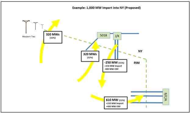
Figure 2: Proposed Protocol - Example of Flows over the ABC Interface, JK Interface, 5018 line and the Western ties
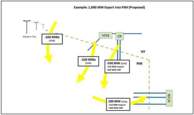
Figure 3: Proposed Protocol - Example of Flows over the ABC Interface, JK Interface, 5018 line and the Western ties
Honorable Kimberly D. Bose January 31, 2017
Page 6
The RTOs also propose to utilize the PARs at the ABC Interface and JK Interface for
Market-to-Market (“M2M”) PAR coordination to minimize congestion across both NYISO and PJM regions. NYISO and PJM already use the Ramapo PARs20 for M2M PAR coordination and propose to introduce the same type of PAR coordination using the ABC PARs21 and Waldwick
PARs22 commencing on May 1, 2017. By combining M2M PAR coordination with the
aggregate scheduling of the ABC Interface, JK Interface and 5018 line, the NYISO and PJM can effectuate aggregate interchange schedules across the PJM-NY AC Proxy Bus in a manner that
also permits the RTOs to manage regional congestion with the full set of available PARs
(referred to as the “NY-NJ PARs”).23
The proposed protocol incorporates the ABC Interface and JK Interface into interchange scheduling and M2M PAR coordination between NYISO and PJM to replace the current nonconforming 1,000 MW Wheel. There are no impacts to procedures or applications (such as Coordinated Transaction Scheduling) other than the proposed changes in this filing.
B. Proposed Interchange Scheduling Process
The RTOs propose to implement interchange by reviewing offers and scheduling
transactions over the redefined PJM-NY AC Proxy Bus. The process will remain substantially similar to today; however, the ABC Interface and JK Interface facilities will be specifically included in the proxy bus definition.24
1. Proposed Interchange Distribution
Based on the result of power flow studies jointly performed by PJM and NYISO,
scheduled interchange will be distributed across the interface facilities based on a static expected interchange distribution of 32% over the Ramapo Interface, 15% over the JK Interface, 21% over the ABC Interface, and 32% over the Western ties. The interchange percentages will then be
further broken down to each PAR-controlled facility. On the 5018 line, each Ramapo PAR will be assigned 16% of interchange. On the JK Interface, each Waldwick PAR will be assigned 5% of interchange. On the ABC Interface, each ABC PAR will be assigned 7% of interchange. If
any of the PARs on these interfaces are out of service, the percentage of interchange normally
assumed to flow over that PAR will instead be assumed to flow over the Western ties. The
proposal allows the RTOs to leverage existing market and modeling concepts over the expanded distribution of expected PJM-NY AC interchange.
20 “Ramapo PARs” refers to the 3500 PAR and 4500 PAR that control flow on the Ramapo Interface.
21 “ABC PARs” refers to the A PAR, B PAR and C PAR that control flow on the ABC Interface.
22 “Waldwick PARs” refers to the E PAR, F PAR and O PAR that control flow on the JK Interface.
23 The NY-NJ PARs consist of the Ramapo PARs, ABC PARs, and the Waldwick PARs.
24 The proposal outlined in this filing is based on the current technology that exists at the ABC Interface and JK
Interface. The NYISO and PJM could revisit this design to determine if interfaces can be individually scheduled if the technology is upgraded or replaced.
Honorable Kimberly D. Bose January 31, 2017
Page 7
The Locational Based Marginal Prices (“LBMPs”) developed for NYISO’s PJM
Keystone Proxy Bus25 and the Locational Marginal Prices (“LMPs”) developed for PJM’s NYIS
Proxy Bus26 will be weighted to include the impacts of imports/exports over the ABC Interface
and JK Interface, much like the weighting that occurs today to include the impacts of
imports/exports over the Ramapo Interface. These proxy buses will be modeled in the NYISO
and PJM markets with the objective that for every MW of total interchange injected at the PJM-
NY AC Proxy Bus in the Day-Ahead Market, and for every MW of incremental change in
interchange injected at the Proxy Bus in the Real-Time Market, 0.21 MW is directed over the
ABC Interface, 0.15 MW is directed over the JK Interface, 0.32 MW is directed over the 5018
line, and the remainder is distributed across the Western ties. The impacts of imports and
exports on the NYISO and PJM transmission systems will be reflected in the proxy bus
LBMPs/LMPs, weighted by the same power flow distribution percentages applied to the
interchange in the market models.
Market Participants will continue to bid in the same manner as they do today in both PJM’s and NYISO’s energy markets. Specifically, there will continue to be a single bidding point for PJM-NY AC Interchange. In the NYISO Day-Ahead Market and Real-Time Market, this will continue to be at the PJM Keystone Proxy Bus. In the PJM Day-ahead and Real-time Energy Markets, this will continue to be at the NYIS Proxy bus. While the bidding location for PJM-NY AC interchange will not change, the scheduling and pricing of the proxy bus will change to include the ABC Interface and JK Interface, as discussed above.
The NYISO and PJM studied several scenarios, with different distribution percentages,
prior to arriving at the proposed distribution. These scenario analyses identified reliability
issues27 in Northern New Jersey as well as delivery limitations when exporting from PJM to the
NYISO on the JK Interface and when exporting from NYISO to PJM on the ABC Interface. The
results identified the potential for severe thermal violations in Northern New Jersey under the
high load and high transfer to New York Summer OATF case, demonstrated a shifting of flows
from the 230 kV system to the 345 kV system, and demonstrated that PAR tap adjustments could
be exhausted prior to achieving the desired flow.28 The results also demonstrated a lack of
operational flexibility under extreme system conditions as phase angle limitations on the
Waldwick PARs did not allow for flows to be adjusted to meet scheduled targets when high
levels of exports into NYISO are assumed. NYISO analyses identified delivery limitations when
exporting to PJM over the ABC Interface after securing for N-1-1 on the NYISO system, and
then attempting further deliveries.
25 “Keystone Proxy Bus” is the name used in the NYISO software to identify the PJM-NY AC Proxy Bus.
26 “NYIS Proxy Bus” is the name used in the PJM software to identify the PJM-NY AC Proxy Bus.
27 See PJM OC presentation: http://www.pjm.com/~/media/committees-groups/committees/oc/20160913/20160913-
item-14-pjm-nyiso-wheel-replacement-overview.ashx.
28 The results were discussed and presented to stakeholders in a joint white paper from the NYISO and PJM, Con
Ed/PSEG Wheel Replacement Proposal, attached hereto as Attachment VII and available at
http://www.nyiso.com/public/webdocs/markets_operations/committees/mc/meeting_materials/2016-12-
21/FINAL%20ConEd%20PSEG%20Wheel%20Replacement%20Proposal%20Whitepaper.pdf.
Honorable Kimberly D. Bose January 31, 2017
Page 8
After identification of reliability issues in Northern New Jersey under the PJM high
export assumption, further studies were performed to identify designs that would allow for
continued support of historical Total Transfer Capability (“TTC”) between the two regions. The
NYISO and PJM conducted studies focused on natural system flows with zero interchange
scheduled between PJM and NYISO and all interface PARs held at neutral tap. Natural system
flow was determined by measuring the flow across the system border as a result of the electrical
characteristics of the transmission system absent any user controlled PAR adjustments under a
balanced generation and load dispatch. The studies focused on summer peak cases and
demonstrated a natural system flow from NYISO to PJM over the JK Interface and from PJM to
NYISO over the ABC Interface. The existence of this natural tendency is unsurprising, since
Con Edison, PSEG, NYISO (including its predecessor, the New York Power Pool) and PJM
planned their systems to accommodate the 1,000 MW Wheel for over 30 years. The RTOs,
therefore, propose to include a natural system flow offset, referred to as an “Operational Base
Flow” or “OBF,” of 400 MW into PJM over the JK Interface and 400 MW into New York on the
ABC Interface when scheduling interchange and when determining target flows.
2. Proposed Operational Base Flow
The proposed initial 400 MW OBF is necessary to address the short-term reliability
issues in Northern New Jersey described above and to maintain historical interface transfer
limits. The RTOs propose to apply an initial OBF of 400 MW in interface flows until
transmission upgrades are completed in Northern New Jersey. Absent the OBF, the TTC
between the two areas would have to be reduced. The OBF is not a firm transmission service on either the NYISO transmission system or the PJM transmission system. The proposed JOA
revisions provide that the OBF will not result in charges from one RTO to the other RTO, or
from one RTO to the other RTO’s Market Participants, except for the settlements described in
the Real-Time Energy Market Coordination and Settlements provisions set forth in Sections 7
and 8 of Schedule D to the JOA. In particular, the NYISO and its Market Participants will not be subjected to PJM Regional Transmission Expansion Plan (“RTEP”) cost allocations as a result of the RTOs’ implementation of an OBF.29
The initial OBF of 400 MW will be applied over the JK Interface from NYISO to PJM
and over the ABC Interface from PJM to NYISO in conjunction with the interchange distribution
percentages discussed above. NYISO and PJM have agreed that the initial OBF will be evenly
distributed across each of the three PARs at the JK Interface, with the expected flow over each
PAR to include one-third of the OBF value. At the ABC Interface, the expected flow over the A
PAR will ordinarily include 25% of the OBF value and the expected flows for the B and C PARs
will each ordinarily include 37.5% of the OBF value. These distribution percentages for the
initial OBF and the interchange distribution percentages were agreed upon by PJM and NYISO
based on the current transmission system and PAR angle limitations experienced on the
Waldwick PARs and ABC PARs. The proposed JOA revisions also allow the RTOs to mutually
agree to modify the OBF MW value or the distribution of the OBF MWs across the PARs.
29 See JOA Section 35.2.1 (proposed definition of OBF).
Honorable Kimberly D. Bose January 31, 2017
Page 9
NYISO and PJM will review the OBF MW value at least annually to determine if modification is
appropriate. The NYISO and PJM will each post, on their respective websites, the OBF values,
in MW, normally applied to each ABC PAR and Waldwick PAR when all of the ABC PARs and
Waldwick PARs are in service. The RTOs will update their website postings if the OBF MW
value or the OBF distribution across the PARs is modified. The OBF posting will also specify
how the OBF MWs are distributed across the in-service NY-NJ PARs when one or more of the
NY-NJ PARs are out of service. The initial OBF value is expected to be reduced to zero MW
within five years, when, as discussed below, system conditions permit reduction of the OBF.
The RTOs propose to include provisions in the JOA that will permit either RTO to
establish a temporary OBF to address a reliability issue until a long-term solution to the
identified reliability issue can be implemented. If one RTO needs to establish a temporary OBF,
the OBF value must be set at a level that both RTOs agree they can reliably support. The RTO
that establishes the OBF must: (1) explain the reliability need to the other RTO; (2) describe how
the OBF addresses the identified reliability need; and (3) identify the expected long-term
solution to address the reliability need. The NYISO and PJM also reviewed the proposed initial
400 MW OBF using these three criteria. Through this review, PJM identified the reliability need
(discussed above). PJM and NYISO examined how the OBF addresses the reliability need by
providing operational flexibility and by allowing the RTOs to utilize higher transfer limits on the
JK Interface and ABC Interface to maintain reliability in Northern New Jersey. The OBF
improves transfer capability and alleviates thermal violations in Northern New Jersey that arise
when distributing interchange across each interface. PJM then identified the Bergen-Linden
Corridor project under development in Northern New Jersey that is expected to obviate the
reliability need for the OBF in the long-term, i.e., within no more than five years. To implement
the initial OBF as well as any future OBF, the facilities on the ABC Interface and JK Interface
are to be functional and operational, consistent with good utility practice.
C. Proposed Market-to-Market PAR Coordination Modifications
The RTOs currently engage in M2M PAR coordination using the Ramapo PARs.
NYISO and PJM propose to incorporate the ABC PARs and Waldwick PARs into M2M PAR coordination commencing May 1, 2017. The ABC PARs and Waldwick PARs were not
previously included in M2M PAR coordination because their primary function was to facilitate delivery of the 1,000 MW Wheel.
M2M PAR coordination is a real-time operations mechanism that signals the PJM and
NYISO operators when the PARs can be used to minimize regional congestion. Moving taps on PARs allows the operators to reduce regional congestion by redistributing flows across the
various AC interfaces between NYISO and PJM. Today, the JOA includes M2M PAR
coordination rules and associated settlement rules that were accepted by the Commission.30 The RTOs propose to modify the JOA by adding the facilities formerly controlled by the wheel
protocol and apply the M2M PAR coordination rules to all NY-NJ PARs.31
30 See New York Independent System Operator, Inc., 138 FERC ¶ 61,192 (2012).
31 See Section 7.2 of Schedule D to the JOA.
Honorable Kimberly D. Bose January 31, 2017
Page 10
The RTOs propose to develop an M2M PAR “target value” for each of the ABC PARs
and Waldwick PARs, similar to what is in place today for the Ramapo PARs. The RTOs will
determine the target flow over each PAR by combining the applicable static percentage of
scheduled interchange, the applicable OBF value, and the applicable percentage of Rockland
Electric Company load (“RECo Load”). The proposed JOA revisions specify the percentage of
interchange used to calculate the interchange factor for each PAR and the percentage of RECo
Load that will be included in the target value calculation for each PAR. The OBF values
normally applied to the ABC PARs and Waldwick PARs will be posted on the RTOs’ websites.
The formula for deriving the target flow at each PAR can be expressed as follows:
Target Flow = Interchange Factor + OBF + RECo Load
For example, if the desired net interchange (based on economic transaction schedules) is 1,300
MW into NYISO, the target flow over the A PAR would be determined as follows: (1300*21%/3
+ (400*25%) + (0%*RECo Load) = 191 MW into NYISO. Consistent with the existing JOA,
80% of RECo Load is included in the target flow toward the NYISO for the 5018 line PARs. An
example of a target flow calculation for a PAR that includes RECo Load could be as follows, if
the total net interchange is 1,300 MW into PJM (i.e., -1,300 MW) and RECo load is 450 MW,
then the target flow on the 3500 PAR (at the Ramapo Interface) is ([-1300*32%]/2 + (0) +
[450*80%]/2) or -28 MW (i.e., 28 MW into PJM).
The RTOs are not proposing to modify service to RECo Load in this filing. The current
construct for serving RECo Load requires PJM to compensate NYISO when serving RECo
causes congestion on the New York system. Eighty percent (80%) of telemetered real-time
RECo Load will continue to be included in the target flows over the Ramapo PARs. When both
Ramapo PARs are in service, 40% of RECo Load will be included in the target value for each
Ramapo PAR. If one Ramapo PAR is out of service, 80% of RECo Load will be included in the
target value for the in-service Ramapo PAR. To the extent the 5018 line and Ramapo PARs are
unable to serve 80% of RECo Load, the power to serve RECo Load will travel from PJM to New
York over the Western ties and across the New York Transmission System to the RECo service
area. The current treatment of RECo Load was added to the JOA in January 2013.32 NYISO
and PJM agree to continue to discuss alternative approaches to serve RECo Load.
M2M PAR settlements between NYISO and PJM currently reflect the effect that the
operation of the Ramapo PARs are having on regional congestion. The RTOs propose to revise
the settlement rules currently set forth in the JOA to include the full effect of all in-service NY-
NJ PARs on regional congestion. Target values, as explained above, are compared to the actual
flow values to determine the M2M PAR settlement component associated with each PAR. This
M2M settlement component accounts for the different impact each PAR has on congestion for
each RTO by multiplying a PAR’s shift factor with the shadow price of each active flowgate.
This resultant is then multiplied by the PAR’s deviation from its target flow to arrive at the M2M
settlement component. Each PAR’s M2M settlement component could reflect a net relief or net
32 See New York Independent System Operator, Inc., 140 FERC ¶ 61,205 (2012).
Honorable Kimberly D. Bose January 31, 2017
Page 11
harm on system congestion. The M2M PAR settlement component will then be netted for all eight NY-NJ PARs, for each interval, to produce a consolidated settlement value.
D. System Planning
The RTOs do not propose any JOA changes with respect to system planning. PJM and
NYISO planning personnel have communicated and will continue to communicate the treatment
of interchange and the OBF in future planning cases through their respective stakeholder
processes.
NYISO will review all relevant data inputs, including the OBF, to establish study
assumptions at the start of each planning study. In general, NYISO planning models
representing the bulk power system from May 1, 2017 through May 31, 2021 will incorporate the 400 MW OBF. Planning models representing the bulk power system beyond June 1, 2021 will assume an OBF of zero MW.
The PJM planning models will assume a zero MW OBF for future cases. PJM reviewed the zero MW OBF methodology with PJM stakeholders at several PJM Planning Committee meetings in 2016. Additionally, PJM reiterated the zero MW OBF assumption for the 2017 RTEP at the recent Transmission Expansion Advisory Committee (“TEAC”) assumptions
meetings in December 2016 and January 2017. PJM’s System Planning Division will annually review the OBF assumption with the TEAC to confirm no changes are needed.
II.Stakeholder Involvement
The JOA revisions proposed in this filing are the product of extensive discussions between the RTOs.
The NYISO and PJM conducted two joint stakeholder meetings on August 15, 2016 and September 16, 2016.
The NYISO formally presented and discussed the proposed revisions with its
stakeholders on numerous occasions prior to the Management Committee (“MC”), in addition to
the two joint stakeholder meetings. Presentations were given at the NYISO Market Issues
Working Group (“MIWG”) meetings held on June 23, 2016, July 21, 2016, August 29, 2016,
September 29, 2016, October 19, 2016 and November 29, 2016. The proposed changes were
also discussed with the NYISO’s Business Issues Committee (“BIC”) on December 14, 2016.
On December 21, 2016, the NYISO’s MC unanimously supported the proposed revisions, with
abstentions.
PJM began discussions with stakeholders in July 2016, and subsequent months, discussed the proposed revisions with them at a high level in November 2016, and also formally presented and discussed the JOA revisions proposed in this filing with its stakeholders at its December 2016 Operating Committee (“OC”), Market Implementation Committee (“MIC”), Planning
Committee (“PC”), and Markets and Reliability Committee (“MRC”) meetings.
Honorable Kimberly D. Bose January 31, 2017
Page 12
III.Description of Proposed Tariff Revisions
A.Proposed Revisions to Section 35.2 of the JOA
The RTOs propose revisions to the definitions section of the JOA and to add several new definitions. Most of the new definitions relate to identifying the facilities on the various AC interfaces between NYISO and PJM. The RTOs propose to define each PAR individually, each interface between the two areas, and the PARs on each interface as a collective group. A set of example definitions is included below for the Ramapo Interface, with similar sets of definitions proposed for the facilities comprising the ABC Interface and JK Interface:
•“3500 PAR” shall mean the 3500 phase angle regulator at the Ramapo station connected
to the 5018 Hopatcong-Ramapo 500 kV line.
•“4500 PAR” shall mean the 4500 phase angle regulator at the Ramapo station connected
to the 5018 Hopatcong-Ramapo 500 kV line.
•“Ramapo Interface” shall mean the transfer path comprised of the 5018 Hopatcong-
Ramapo 500 kV tie line between PJM and NYISO.
•“Ramapo PARs” shall mean the 3500 PAR and 4500 PAR that control flow on the
Ramapo Interface.
The RTOs also propose a new definition to describe all of the PARs on the border between NYISO and PJM and a definition for Operational Base Flow.
• “NY-NJ PARs” shall mean, individually and/or collectively, the ABC PARs, the
Ramapo PARs, and the Waldwick PARs, all of which are components of the NYISO -
PJM interface.
• “Operational Base Flow” or “OBF” shall mean an equal and opposite MW offset of
power flows over the Waldwick PARs and ABC PARs to account for natural system
flows over the JK Interface and the ABC Interface in order to facilitate the reliable
operation of the NYISO and/or PJM transmission systems. The OBF is not a firm
transmission service on either the NYISO transmission system or on the PJM
transmission system. The OBF shall not result in charges from one Party to the other
Party, or from one Party to the other Party’s Market Participants, except for the
settlements described in the Real-Time Energy Market Coordination and Settlements
provisions set forth in Sections 7 and 8 of Schedule D to this Agreement. In particular,
the NYISO and its Market Participants shall not be subjected to PJM Regional
Transmission Expansion Plan (“RTEP”) cost allocations as a result of the OBF.
The RTOs propose to remove references to Schedule C to the JOA, which contains the Operating Protocol for the Implementation of ConEd - PJM Transmission Service Agreements. In addition, the RTOs propose several types of ministerial revisions that appear throughout the JOA, including use of new defined terms and improved consistency of internal references to
other sections of the JOA.
Honorable Kimberly D. Bose January 31, 2017
Page 13
B. Proposed Revisions to Section 35.6 of the JOA
PJM and NYISO rely on emergency assistance during extreme weather conditions and peak load days, as well as other conservative operating events. The RTOs propose to add a new subsection related to emergency conditions. The new language describes the expectations for PAR operation during emergencies and allows the NYISO and PJM to implement appropriate emergency procedures during system emergencies on either the NYISO or PJM system. This assistance during emergency conditions provides both RTOs with a higher level of reliability, which preserves load and reserve margins during emergency events.
C. Proposed Revisions to Sections 35.12, 35.20, and 35.21 of the JOA
The RTOs propose minor revisions to Sections 35.12, 35.20, and 35.21 of the JOA.
Revisions to Section 35.12 include updated references to PARs based on new defined terms and a ministerial revision to use an existing defined term. In Section 35.20, the RTOs propose to
update the contact information in the Notices section and to update the signatories named at the end of the section.
JOA Section 35.21 provides a list of the NY/PJM Interconnection Facilities. With this filing, the RTOs propose to add two new interconnection facility descriptions and to update the names of four existing interconnection facilities.
D. Proposed Revisions to Section 35.22 of the JOA
The RTOs propose to delete Section 35.22 of the JOA. This entire section describes the Operating Protocol for the implementation of the 1,000 MW Wheel. Termination of the 1,000 MW Wheel TSAs on April 30, 2017 will make this section obsolete.
E. Proposed Revisions to Section 35.23 of, Schedule D to, the JOA
Section 35.23 of, Schedule D to, the JOA sets forth the RTOs’ proposed rules for real-
time energy market coordination and M2M PAR coordination. The RTOs propose to revise
Schedule D to incorporate the ABC PARs and Waldwick PARs into energy scheduling and
M2M.
Throughout Section 35.23, the RTOs propose to update references to PARs based on new defined terms, remove references to Schedule C of the JOA, the Operating Protocol for the
Implementation of ConEd - PJM Transmission Service Agreements, and improve consistency of internal references within the JOA.
Section 7.2—the proposed revisions describe operation of the NY-NJ PARs. PJM and
NYISO have operational control of the NY-NJ PARs, while PSEG and Con Edison have
physical control. PJM and NYISO will make reasonable efforts to minimize movement of the
PARs to preserve their long-term availability. The proposed revisions also provide that the
Honorable Kimberly D. Bose January 31, 2017
Page 14
facilities comprising the ABC Interface and JK Interface must be operational to implement M2M PAR coordination and the initial and any future OBF on them.
Section 7.2.1—the proposed revisions define the target value formula for real-time
operation and for settlement purposes that will be used for each of the NY-NJ PARs. The target value formula is made up of the following terms: an interchange factor, the Operational Base Flow (or OBF) and RECo Load. The proposed descriptions of the formula terms identify which terms apply to which PARs. The target values for the ABC PARs and Waldwick PARs will include an interchange factor and a portion of the OBF value. The target values for the Ramapo PARs will include an interchange factor and a portion of RECo Load.
The OBF description identifies the initial 400 MW OBF described above and the
expectation that the OBF will be reduced to zero MW by June 1, 2021. Inclusion of the initial
OBF alleviates thermal violations and improves energy transfers, allowing for continuation of
historical interface transfer limits. The OBF description also specifies the process and criteria
for the RTOs to establish a temporary OBF to address a reliability issue, the ability for the RTOs
to mutually agree to modify the OBF, the obligation for the RTOs to post the OBF values on
their websites and the obligation for the RTOs to post the methodology used to reduce the OBF
under facility outage conditions. The RTOs will review the OBF MW value at least annually.
The proposed OBF description states that either RTO may establish a temporary OBF to address a reliability issue until a long-term solution to the identified reliability issue can be
implemented. Any temporary OBF that is established must be at a level that both RTOs can reliably support. The RTO that establishes the OBF must: (1) explain the reliability need to the other RTO; (2) describe how the OBF addresses the identified reliability need; and (3) identify the expected long-term solution to address the reliability need.
Sections 7.2.2 and 8.1—the proposed revisions apply the existing cost of congestion calculation and information used to calculate M2M settlements provisions to all the NY-NJ PARs, instead of just the Ramapo PARs.
Section 8.3—the RTOs propose to revise the M2M PARs settlement calculation to
incorporate all of the NY-NJ PARs. Comparison of the actual real-time flow to the target flow will now occur for each NY-NJ PAR. The RTO that is under-delivering MWs across a PAR
compared to the target value may be required to compensate the other RTO based on the
difference between the actual and target flows times the transmission congestion costs of the
RTO receiving the MWs. The M2M PARs settlement will be one net value for each interval,
inclusive of all the PARs.
Section 8.3.1—the proposed revisions update references to PARs based on new defined
terms, remove references to Schedule C of the JOA, the Operating Protocol for the
Implementation of ConEd - PJM Transmission Service Agreements, and clarify that the RTOs
are excused from settlements during the first fifteen minutes that a Storm Watch is in effect.
Honorable Kimberly D. Bose January 31, 2017
Page 15
Section 8.4—the proposed revisions clarify that the existing combined M2M settlement will include all the NY-NJ PARs, instead of just the Ramapo PARs.
Section 10.1.8— the proposed revisions update references to PARs based on new defined terms and provide that the PAR settlement component of overall M2M settlements will be
suspended when a request for taps on a NY-NJ PAR is refused by the other RTO.
Section 10.1.9—the proposed revisions state that the RTOs will suspend PAR settlements for a NY-NJ PAR that is out of service, bypassed or if the RTOs mutually agree that the PAR is incapable of facilitating interchange.
F. Proposed Revisions to NYISO Services Tariff Section 17.1
The revisions proposed in this section are only offered by the NYISO and are not subject
to the enclosed PJM Certificate of Concurrence. The NYISO proposes to update the name of the
Hopatcong-Ramapo interconnection, describe the expected flow over the ABC Interface and JK
Interface, and remove references to Schedule C of the JOA, the Operating Protocol for the
Implementation of ConEd - PJM Transmission Service Agreements, and its associated
processes.
IV.Proposed Effective Date
The RTOs respectfully request that the Commission permit the proposed JOA revisions
to become effective on May 1, 2017. The NYISO requests that its proposed Services Tariff
revisions also become effective on May 1, 2017. The RTOs respectfully request that the
Commission issue an order on this filing by April 1, 2017, sixty days from the date of this filing,
to permit the orderly implementation of the enclosed revisions on May 1, 2017, or let this filing
go into effect pursuant to Section 205 of the Federal Power Act.33 If the Commission does not
issue an order addressing the substance of the revisions proposed in this filing by April 1, then
the RTOs are prepared to implement the revisions proposed herein on May 1, 2017.34 Without
these revisions, the RTOs would have no tariff authority to implement economic interchange
over the ABC Interface and JK Interface or to utilize M2M PAR coordination with the PARs at
these interfaces. In the absence of the 1,000 MW Wheel, not utilizing these two interfaces for
economic interchange would reduce the exchange of power between the relatively congested
Southeastern New York and Northern New Jersey areas. If the ABC Interface and JK Interface
are not used to transfer power between the regions, then additional power would be forced over
the Western ties and increase congestion on the already congested transmission facilities
33 The parties note that should the Commission lack a quorum to affirmatively act on this filing by the requested
effective date, it is reasonable for the Commission to allow these scheduling protocols to go into effect given the
demonstrated benefits detailed in this letter. Because this filing implements a revised scheduling protocol, any
future Commission action addressing this protocol, which require changes, could be addressed prospectively by
NYISO and PJM. But given the termination of the wheel service by Con Edison, it is reasonable for the
Commission to allow this filing to go into effect by operation of law should the Commission lack a quorum to issue
an affirmative order in this case.
34 See 16 U.S.C. §824d.
Honorable Kimberly D. Bose January 31, 2017
Page 16
traveling from west to east across New York State, Pennsylvania and New Jersey. The
consequences would be both costly and inefficient. The RTOs’ further respectfully request that any changes to the proposed revisions the Commission instructs in an order issued after April 1, 2017 take effect on a prospective basis only.
V.Documents Enclosed
The RTOs enclose with this transmittal letter:
1. A clean version of the RTOs’ proposed revisions to their JOA (Attachment I);
2. A blacklined version of the RTOs’ proposed revisions to their JOA (Attachment II);
3. PJM’s concurrence letter, concurring with the proposed revisions to the JOA
(Attachment III);
4. A clean version of the NYISO’s proposed revisions to its Services Tariff (Attachment
IV);
5. A blacklined version of the NYISO’s proposed revisions to its Services Tariff
(Attachment V);
6. A letter to Andrew Ott from Milovan Blair dated April 28, 2016 (Attachment VI);
and
7. A joint white paper from the NYISO and PJM, Con Ed/PSEG Wheel Replacement
Proposal (Attachment VII).
VI.Service
A.NYISO Service
This filing will be posted on the NYISO’s website at www.nyiso.com. In addition, the
NYISO will email an electronic copy of this filing to each of its customers, to each participant on its stakeholder committees, to the New York Public Service Commission, and to the New Jersey Board of Public Utilities.
B.PJM Service
PJM has served a copy of this filing on all PJM Members and on all state utility
regulatory commissions in the PJM Region by posting this filing electronically. In accordance
with the Commission’s regulations,35 PJM will post a copy of this filing to the FERC filings
section of its internet site, located at the following link: http://www.pjm.com/documents/ferc-
35 See 18C.F.R §§ 35.2(e) and 385.2010(f)(3).
Honorable Kimberly D. Bose January 31, 2017
Page 17
manuals/ferc-filings.aspx with a specific link to the newly-filed document, and will send an e-
mail on the same date as this filing to all PJM Members and all state utility regulatory
commissions in the PJM Region36 alerting them that this filing has been made by PJM and is
available by following such link. If the document is not immediately available by using the
referenced link, the document will be available through the referenced link within 24 hours of the
filing. Also, a copy of this filing will be available on the FERC’s eLibrary website located at the
following link: http://www.ferc.gov/docs-filing/elibrary.asp in accordance with the
Commission’s regulations and Order No. 714.
VII. Correspondence and Communications
Please send all correspondence and communications regarding this filing to:
Craig Glazer*
VP - Federal Government Policy PJM Interconnection, L.L.C.
1200 G Street, N.W., Suite 600 Washington, D.C. 20005
(202) 423-4743
Raymond Stalter*
Director, Regulatory Affairs
New York Independent System
Operator, Inc.
10 Krey Boulevard Rensselaer, NY 12144 (518) 356-8503
*Persons designated for receipt of service37
Jacqulynn Hugee*
Associate General Counsel PJM Interconnection, L.L.C. 2750 Monroe Blvd.
Audubon, PA 19403 (610) 666-8208
Alex M. Schnell
Assistant General Counsel/
Registered Corporate Counsel
James H. Sweeney*
Attorney
New York Independent System
Operator, Inc.
10 Krey Boulevard Rensselaer, NY 12144 (518) 356-7659
36 PJM already maintains, updates and regularly uses e-mail lists for all PJM Members and affected state commissions.
37 The RTOs request a limited waiver of Rule 203(b)(3) of the Commission’s Rules of Practice and Procedure to permit each RTO to designate two representatives to receive service in this proceeding.
Honorable Kimberly D. Bose January 31, 2017
Page 18
VIII. Conclusion
The RTOs respectfully request that the Commission accept the attached JOA and tariff
revisions for filing with an effective date that is consistent with Section IV of this filing letter.
Respectfully submitted,
/s/ James H. Sweeney
Alex M. Schnell, Assistant General Counsel/
Registered Corporate Counsel
James H. Sweeney, Attorney
New York Independent System Operator, Inc.
cc:Michael Bardee
Nicole Buell
Anna Cochrane
Jignasa Gadani
Michael Goldenberg Kurt Longo
Valerie Martin
Max Minzner
David Morenoff
Daniel Nowak
David Ortiz
Larry Parkinson
J. Arnold Quinn Douglas Roe
Peter Rosalevich Kathleen Schnorf Jamie Simler
Gary Will
/s/ Jacqulynn Hugee
Jacqulynn Hugee, Associate General
Counsel
Craig Glazer, VP - Fed. Government Policy PJM Interconnection, L.L.C.
35.2Abbreviations, Acronyms, Definitions and Rules of Construction
In this Agreement, the following words and terms shall have the meanings (such
meanings to be equally applicable to both the singular and plural forms) ascribed to them in this Section 35.2. Any undefined, capitalized terms used in this Agreement shall have the meaning given under industry custom and, where applicable, in accordance with Good Utility Practices or the meaning given to those terms in the tariffs of PJM and NYISO on file at FERC.
35.2.1 Abbreviations, Acronyms and Definitions
“3500 PAR” shall mean the 3500 phase angle regulator at the Ramapo station connected to the 5018 Hopatcong-Ramapo 500 kV line.
“4500 PAR” shall mean the 4500 phase angle regulator at the Ramapo station connected to the 5018 Hopatcong-Ramapo 500 kV line.
“A PAR” shall mean the phase angle regulator located a the Goethals station connected to the A2253 Linden-Goethals 230 kV line.
“ABC Interface” shall mean the transfer path comprised of the A2253 Linden-Goethals, B3402 Hudson-Farragut and C3403 Marion-Farragut tie lines between PJM and NYISO.
“ABC PARs” shall mean the A PAR, B PAR and C PAR that control flow on the ABC Interface.
“AC” shall mean alternating current.
“Affected Party” shall mean the electric system of the Party other than the Party to which a
request for interconnection or long-term firm delivery service is made and that may be affected by the proposed service.
“Agreement” shall mean this document, as amended from time to time, including all attachments, appendices, and schedules.
“Area Control Error” or “ACE” shall mean the instantaneous difference between a Balancing Authority’s net actual and scheduled interchange, taking into account the effects of Frequency Bias and correction for meter error.
“Available PAR” shall mean, for purposes of Section 8.3.1 of Schedule D to this Agreement, a NY-NJ PAR that is not subject to any of the following circumstances:
(1) a PAR that is not operational and is unable to be moved;
(2) a PAR that is technically “in-service” but is being operated in an outage configuration and is only capable of feeding radial load;
(3) a PAR that is tapped-out in a particular direction is not available in the tapped-out direction;
(4) if the maximum of 400 taps/PAR/month is exceeded at an ABC PAR, Ramapo PAR or a Waldwick PAR, and the relevant asset owner restricts the RTOs from
taking further taps on the affected PAR, then the affected PAR shall not be available until NYISO and PJM agree to and implement an increased bandwidth in accordance with Section 7.2 of Schedule D to this Agreement;
(5) PJM is permitted to reserve up to three taps at each end of the PAR tap range of each Waldwick PAR to secure the facilities on a post contingency basis, a Waldwick PAR shall not be considered available if a tap move would require the use of a
reserved PAR tap; or
(6) NYISO is permitted to reserve up to two taps at each end of the tap range of each ABC PAR and Ramapo PAR to secure the facilities on a post contingency basis, an ABC or Ramapo PAR shall not be considered available if a tap move would require the use of a reserved PAR tap.
PJM or NYISO may choose to use PAR taps they are permitted to reserve to perform M2M coordination, but they are not required to do so.
“Available Flowgate Capability” or “AFC” shall mean the rating of the applicable Flowgate
less the projected loading across the applicable Flowgate less TRM and CBM. The firm AFC is
calculated with only the appropriate Firm Transmission Service reservations (or interchange
schedules) in the model, including recognition of all roll-over Transmission Service rights. Non-
firm AFC is determined with appropriate firm and non-firm reservations (or interchange
schedules) modeled.
“Available Transfer Capability” or “ATC” shall mean a measure of the transfer capability remaining in the physical transmission network for further commercial activity over and above already committed uses.
“B PAR” shall mean the phase angle regulator located at the Farragut station connected to the B3402 Hudson-Farragut 345 kV line.
“Balancing Authority” or “BA” shall mean the responsible entity that integrates resource plans ahead of time, maintains load-interchange-generation balance within a Balancing Authority
Area, and supports interconnection frequency in real-time.
“Balancing Authority Area” or “BAA” shall mean the collection of generation, transmission, and loads within the metered boundaries of the Balancing Authority. The Balancing Authority maintains load-resource balance within this area.
“Bulk Electric System” shall have the meaning provided for in the NERC Glossary of Terms
used in Reliability Standards, as it may be amended, supplemented, or restated from time to time.
“C PAR” shall mean the phase angle regulator located at the Farragut station connected to the C3403 Marion-Farragut 345 kV line.
“Capacity Benefit Margin” or “CBM” shall mean the amount of firm transmission transfer
capability preserved by the transmission provider for Load-Serving Entities (“LSEs”), whose
loads are located on that Transmission Service Provider’s system, to enable access by the LSEs
to generation from interconnected systems to meet generation reliability requirements.
Preservation of CBM for an LSE allows that entity to reduce its installed generating capacity
below that which may otherwise have been necessary without interconnections to meet its
generation reliability requirements. The transmission transfer capability preserved as CBM is
intended to be used by the LSE only in times of emergency generation deficiencies.
“CIM” shall mean Common Infrastructure Model.
“Confidential Information” shall have the meaning stated in Section 35.8.1.
“Control Area(s)” shall mean an electric power system or combination of electric power systems to which a common automatic generation control scheme is applied.
“Control Performance Standard” or “CPS” shall mean the reliability standard that sets the limits of a Balancing Authority’s Area Control Error over a specified time period.
“Coordinated Transaction Scheduling” or “CTS” shall mean the market rules that allow
transactions to be scheduled based on a bidder’s willingness to purchase energy from a source in either the NYISO or PJM Control Area and sell it at a sink in the other Control Area if the
forecasted price at the sink minus the forecasted price at the corresponding source is greater than or equal to the dollar value specified in the bid.
“Coordination Committee” shall mean the jointly constituted PJM and NYISO committee
established to administer the terms and provisions of this Agreement pursuant to Section 35.3.2.
“CTS Interface Bid” shall mean: (1) in PJM, a unified real-time bid to simultaneously purchase
and sell energy on either side of a CTS Enabled Interface in accordance with the procedures of
Section 1.13 of Schedule 1 of the Amended and Restated Operating Agreement of PJM, L.L.C.;
and (2) in NYISO, a real-time bid provided by an entity engaged in an external transaction at a
CTS Enabled Interface, as more fully described in NYISO Services Tariff Section 2.3.
“Delivery Point” shall mean each of the points of direct Interconnection between PJM and the NYISO Balancing Authority Areas. Such Delivery Point(s) shall include the Interconnection Facilities between the PJM and the New York Balancing Authority Areas.
“DC” shall mean direct current.
“Disclosing Party” shall have the meaning stated in Section 35.8.7. “Dispute” shall have the meaning stated in Section 35.15.
“Disturbance Control Standard” or “DCS” shall mean the reliability standard that sets the time limit following a disturbance within which a balancing authority must return its Area Control Error to within a specified range.
“E PAR” shall mean the phase angle regulator located at the Waldwick station on the E-2257 Waldwick-Hawthorne 230 kV line.
“Economic Dispatch” shall mean the sending of dispatch instructions to generation units to minimize the cost of reliably meeting load demands.
“Effective Date” shall have the meaning stated in Section 35.19.1.
“Emergency” shall mean any abnormal system condition that requires remedial action to prevent or limit loss of transmission or generation facilities that could adversely affect the reliability of the electricity system.
“Emergency Energy” shall mean energy supplied from Operating Reserve or electrical
generation available for sale in New York or PJM or available from another Balancing Authority Area. Emergency Energy may be provided in cases of sudden and unforeseen outages of
generating units, transmission lines or other equipment, or to meet other sudden and unforeseen circumstances such as forecast errors, or to provide sufficient Operating Reserve. Emergency Energy is provided pursuant to this Agreement and the Inter Control Area Transactions
Agreement dated May 1, 2000 and priced according to Section 35.6.4 of this Agreement and said Inter Control Area Transactions Agreement.
“EMS” shall mean the respective Energy Management Systems utilized by the Parties to manage the flow of energy within their Regions.
“External Capacity Resource” shall mean: (1) for NYISO, (a) an entity (e.g., Supplier,
Transmission Customer) or facility (e.g., Generator, Interface) located outside the NYCA with
the capability to generate or transmit electrical power, or the ability to control demand at the
direction of the NYISO, measured in megawatts or (b) a set of Resources owned or controlled by
an entity within a Control Area, not the NYCA, that also is the operator of such Control Area;
and (2) for PJM, a generation resource located outside the metered boundaries of the PJM
Region (as defined in the PJM Tariff) that meets the definition of Capacity Resource in the PJM Tariff or PJM’s governing agreements filed with the Commission.
“F PAR” shall mean the phase angle regulator located at the Waldwick station on the F-2258 Waldwick-Hillsdale 230 kV line.
“FERC” or “Commission” shall mean the Federal Energy Regulatory Commission or any successor agency thereto.
“Flowgate” shall mean a representative modeling of facilities or groups of facilities that may act as potential constraint points.
“Force Majeure” shall mean an event of force majeure as described in Section 35. 20.1.
“Generator to Load Distribution Factor” or “GLDF” shall mean a generator’s impact on a Flowgate while serving load in that generator’s Balancing Authority Area.
“Good Utility Practice” shall mean any of the practices, methods and acts engaged in or
approved by a significant portion of the North American electric utility industry during the relevant time period, or any of the practices, methods and acts which, in the exercise of
reasonable judgment in light of the facts known at the time the decision was made, could have been expected to accomplish the desired result consistent with good business practices,
reliability, safety and expedition. Good Utility Practice is not intended to be limited to the
optimum practice, method, or act to the exclusion of all others, but rather to be acceptable
practices, methods, or acts generally accepted by NERC.
“Governmental Authority” shall mean any federal, state, local or other governmental
regulatory or administrative agency, court, commission, department, board, or other
governmental subdivision, legislature, rulemaking board, tribunal, or other governmental
authority having jurisdiction over the Parties, their respective facilities, or the respective services they provide, and exercising or entitled to exercise any administrative, executive, police, or
taxing authority or power.
“ICCP”, “ISN” and “ICCP/ISN” shall mean those common communication protocols adopted to standardize information exchange.
“IDC” shall mean the NERC Interchange Distribution Calculator used for identifying and requesting congestion management relief.
“Indemnifying Party” shall have the meaning stated in Section 35.20.3. “Indemnitee” shall have the meaning stated in Section 35.20.3
“Intellectual Property” shall mean (i) ideas, designs, concepts, techniques, inventions,
discoveries, or improvements, regardless of patentability, but including without limitation
patents, patent applications, mask works, trade secrets, and know-how; (ii) works of authorship, regardless of copyright ability, including copyrights and any moral rights recognized by law; and (iii) any other similar rights, in each case on a worldwide basis.
“Intentional Wrongdoing” shall mean an act or omission taken or omitted by a Party with knowledge or intent that injury or damage could reasonably be expected to result.
“Interconnected Reliability Operating Limit” or “IROL” shall mean the value (such as MW, MVAR, Amperes, Frequency, or Volts) derived from, or a subset of, the System Operating
Limits, which if exceeded, could expose a widespread area of the bulk electrical system to
instability, uncontrolled separation(s) or cascading outages.
“Interconnection” shall mean a connection between two or more individual Transmission Systems that normally operate in synchronism and have interconnecting intertie(s).
“Interconnection Facilities” shall mean the Interconnection facilities described in Schedule A.
“Intermediate Term Security Constrained Economic Dispatch” shall mean PJM’s algorithm
that performs various functions, including but not limited to forecasting dispatch and LMP
solutions based on current and projected system conditions for up to several hours into the future.
“ISO” shall mean Independent System Operator.
“JK Interface” shall mean the transfer path comprised of the JK Ramapo-South MahwahWaldwick tie lines between PJM and NYISO.
“kV” shall mean kilovolt of electric potential.
“LEC Adjusted Market Flow” shall mean the real-time Market Flow incorporating the observed operation of the PARs at the Michigan-Ontario border.
“Locational Marginal Price” or “LMP” shall mean the market clearing price for energy at a
given location in a Party’s RC Area, and “Locational Marginal Pricing” shall mean the processes related to the determination of the LMP.
“Losses” shall have the meaning stated in Section 35.20.3.
“M2M” shall mean the market-to-market coordination process set forth in Schedule D to this Agreement.
“M2M Entitlement” shall mean a Non-Monitoring RTO’s share of a M2M Flowgate’s total
capability to be used for settlement purposes that is calculated pursuant to Section 6 of Schedule D to this Agreement.
“M2M Event” shall mean the period when both Parties are operating under M2M as defined and set forth in Schedule D to this Agreement.
“M2M Flowgate” shall mean Flowgates where constraints are jointly monitored and coordinated as defined and set forth in Schedule D to this Agreement.
“Market Flows” shall mean the calculated energy flows on a specified Flowgate as a result of dispatch of generating resources serving load within an RTO’s market.
“Market Participant” shall mean an entity that, for its own account, produces, transmits, sells,
and/or purchases for its own consumption or resale capacity, energy, energy derivatives and
ancillary services in the wholesale power markets. Market Participants include transmission
service customers, power exchanges, Transmission Owners, load serving entities, loads, holders
of energy derivatives, generators and other power suppliers and their designated agents.
“Metered Quantity” shall mean apparent power, reactive power, active power, with associated time tagging and any other quantity that may be measured by a Party’s Metering Equipment and that is reasonably required by either Party for Security reasons or revenue requirements.
“Metering Equipment” shall mean the potential transformers, current transformers, meters, interconnecting wiring and recorders used to meter any Metered Quantity.
“Monitoring RTO” shall mean the Party that has operational control of a M2M Flowgate.
“Multiregional Modeling Working Group” or “MMWG” shall mean the NERC working group that is charged with multi-regional modeling.
“Mutual Benefits” shall mean the transient and steady-state support that the integrated
generation and Transmission Systems in PJM and New York provide to each other inherently by virtue of being interconnected as described in Section 35.4 of this Agreement.
“MVAR” shall mean megavolt ampere of reactive power.
“MW” shall mean megawatt of capacity.
“NAESB” shall mean North American Energy Standards Board or its successor organization.
“NERC” shall mean the North American Electricity Reliability Corporation or its successor organization.
“Network Resource” shall have the meaning as provided in the NYISO OATT, for such resources located in New York, and the meaning as provided in the PJM OATT, for such resources located in PJM.
“New Year Market Flow” shall mean the Market Flow incorporating the transmission topology that includes all pre-existing Transmission Facilities and all new or upgraded Transmission
Facilities whose impact on M2M Entitlements has been previously evaluated and incorporated, and all new or upgraded Transmission Facilities whose impact on M2M Entitlements is being evaluated in the current evaluation step.
“Non-Monitoring RTO” shall mean the Party that does not have operational control of a M2M Flowgate.
“Notice” shall have the meaning stated in Section 35. 20.22.
“NPCC” shall mean the Northeast Power Coordinating Council, Inc., including the NPCC Cross Border Regional Entity (“CBRE”), or their successor organizations.
“NY-NJ PARs” shall mean, individually and/or collectively, the ABC PARs, the Ramapo
PARs, and the Waldwick PARs, all of which are components of the NYISO - PJM interface.
“NYISO” shall have the meaning stated in the preamble of this Agreement.
“NYISO Code of Conduct” shall mean the rules, procedures and restrictions concerning the
conduct of the ISO directors and employees, contained in Attachment F to the NYISO OATT.
“NYISO Market Monitoring Plan” shall refer to Attachment O to the NYISO Services Tariff.
“NYISO Tariffs” shall mean the NYISO OATT and the NYISO Market Administration and Control Area Services Tariff (“Services Tariff”), collectively.
“NYSRC” shall mean the New York State Reliability Council.
“NYSRC Reliability Rules” shall mean the rules applicable to the operation of the New York Transmission System. These rules are based on Reliability Standards adopted by NERC and NPCC, but also include more specific and more stringent rules to reflect the particular
requirements of the New York Transmission System.
“O PAR” shall mean the phase angle regulator located at the Waldwick station on the O-2267 Waldwick-Fairlawn 230kV line.
“OASIS” shall mean the Open Access Same-Time Information System required by FERC for
the posting of market and transmission data on the Internet websites of PJM and NYISO.
“OATT” shall mean the applicable Open Access Transmission Tariffs on file with FERC for PJM and NYISO.
“Operating Entity” shall mean an entity that operates and controls a portion of the bulk
transmission system with the goal of ensuring reliable energy interchange between generators, loads, and other operating entities.
“Operating Instructions” shall mean the operating procedures, steps, and instructions for the operation of the Interconnection Facilities established from time to time by the Coordination Committee or the PJM and NYISO individual procedures and processes and includes changes from time to time by the Coordination Committee to such established procedures, steps and instructions exclusive of the individual procedures.
“Operational Base Flow” or “OBF” shall mean an equal and opposite MW offset of power
flows over the Waldwick PARs and ABC PARs to account for natural system flows over the JK
Interface and the ABC Interface in order to facilitate the reliable operation of the NYISO and/or
PJM transmission systems. The OBF is not a firm transmission service on either the NYISO
transmission system or on the PJM transmission system. The OBF shall not result in charges
from one Party to the other Party, or from one Party to the other Party’s Market Participants,
except for the settlements described in the Real-Time Energy Market Coordination and
Settlements provisions set forth in Sections 7 and 8 of Schedule D to this Agreement. In
particular, the NYISO and its Market Participants shall not be subjected to PJM Regional
Transmission Expansion Plan (“RTEP”) cost allocations as a result of the OBF.
“Operating Reserve” shall mean generation capacity or load reduction capacity which can be called upon on short notice by either Party to replace scheduled energy supply which is
unavailable as a result of an unexpected outage or to augment scheduled energy as a result of unexpected demand or other contingencies.
“Operational Control” shall mean Security monitoring, adjustment of generation and
transmission resources, coordinating and approval of changes in transmission status for
maintenance, determination of changes in transmission status for reliability, coordination with other Balancing Authority Areas and Reliability Coordinators, voltage reductions and load shedding, except that each legal owner of generation and transmission resources continues to physically operate and maintain its own facilities.
“OTDF” shall mean the electric PTDF with one or more system facilities removed from service (i.e., outaged) in the post-contingency configuration of a system under study.
“Outages” shall mean the planned unavailability of transmission and/or generation facilities dispatched by PJM or the NYISO, as described in Section 35.9 of this Agreement.
“PAR” shall mean phase angle regulator.
“PAR Shift Factor” or “PSF”, shall mean the PAR’s impact on a Flowgate measured as the ratio of Flowgate flow change in MW to PAR schedule change in MW.
“Party” or “Parties” refers to each party to this Agreement or both, as applicable. “PJM” has the meaning stated in the preamble of this Agreement.
“PJM Code of Conduct” shall mean the code of ethical standards, guidelines and expectations for PJM’s employees, officers and Board Members in their transactions and business dealings on behalf of PJM as posted on the PJM website and as may be amended from time to time.
“PJM Tariffs” shall mean the PJM OATT and the PJM Amended and Restated Operating Agreement, collectively.
“Power Transfer Distribution Factor” or “PTDF” shall mean a measure of the responsiveness or change in electrical loadings on Transmission Facilities due to a change in electric power transfer from one area to another, expressed in percent (up to 100%) of the change in power transfer in the pre-contingency configuration of a system under study.
“Ramapo Interface” shall mean the transfer path comprised of the 5018 Hopatcong-Ramapo 500 kV tie line between PJM and NYISO.
“Ramapo PARs” shall mean the 3500 PAR and 4500 PAR that control flow on the Ramapo Interface.
“Real-Time Commitment” shall mean NYISO’s multi-period security constrained unit commitment and dispatch model, as defined in the NYISO Tariffs.
“Reference Year Market Flow” shall mean the Market Flow based on a transmission topology
that includes all pre-existing Transmission Facilities and all new or upgraded Transmission
Facilities whose impact on M2M Entitlements has been previously evaluated and incorporated.
“Region” shall mean the Control Areas and Transmission Facilities with respect to which a Party serves as RTO or Reliability Coordinator under NERC policies and procedures.
“Regulatory Body” shall have the meaning stated in Section 35.20.21.
“Reliability Coordinator” or “RC” shall mean the entity that is the highest level of authority
who is responsible for the reliable operation of the Bulk Electric System, has the wide area view
of the Bulk Electric System, and has the operating tools, processes and procedures, including the
authority to prevent or mitigate emergency operating situations in both next day analysis and
real-time operations. The Reliability Coordinator has the purview that is broad enough to enable
the calculation of Interconnection Reliability Operating Limits, which may be based on the
operating parameters of transmission systems beyond any Transmission Operator’s vision.
“Reliability Coordinator Area” shall mean that portion of the Bulk Electric System under the purview of the Reliability Coordinator.
“Reliability Standards” shall mean the criteria, standards, rules and requirements relating to reliability established by a Standards Authority.
“RFC” shall mean ReliabilityFirst Corporation.
“RTO” shall mean Regional Transmission Organization. For ease of reference, the New York
Independent System Operator, Inc., may be referred to as an RTO in this Agreement and the
NYISO and PJM may be referred to collectively as the “RTOs” or the “participating RTOs.”
“Schedule” shall mean a schedule attached to this Agreement and all amendments, supplements, replacements and additions hereto.
“SDX System” shall mean the system used by NERC to exchange system data.
“Security” shall mean the ability of the electric system to withstand sudden disturbances
including, without limitation, electric short circuits or unanticipated loss of system elements.
“Security Limits” shall mean operating electricity system voltage limits, stability limits and thermal ratings.
“SERC” shall mean SERC Reliability Corporation or its successor organization.
“Shadow Price” shall mean the marginal value of relieving a particular constraint which is
determined by the reduction in system cost that would result from an incremental relaxation of that constraint.
“Standards Authority” shall mean NERC, and the NERC regional entities with governance
over PJM and NYISO, any successor thereof, or any other agency with authority over the Parties
regarding standards or criteria to either Party relating to the reliability of Transmission Systems.
“Standards Authority Standards” shall have the meaning stated in Section 35.5.2.
“State Estimator” shall mean a computer model that computes the state (voltage magnitudes and angles) of the Transmission System using the network model and real-time measurements. Line flows, transformer flows, and injections at the busses are calculated from the known state and the transmission line parameters. The State Estimator has the capability to detect and
identify bad measurements.
“Storm Watch” shall mean actual or anticipated severe weather conditions under which regionspecific portions of the New York State Transmission System are operated in a more
conservative manner by reducing transmission transfer limits.
“Supplying Party” shall have the meaning stated in Section 35.8.2.
“System Operating Limit” or “SOL” shall mean the value (such as MW, MVAR, Amperes,
Frequency, or Volts) that satisfies the most limiting of the prescribed operating criteria for a
specified system configuration to ensure operation within acceptable reliability criteria.
“Target Value” shall have the meaning stated in Section 7.2 of Schedule D to this Agreement. “Third Party” refers to any entity other than a Party to this Agreement.
“TLR” shall mean the NERC Transmission Loading Relief Procedures used in the Eastern Interconnection as specified in NERC Operating Policies.
“Transmission Adjusted Market Flow” shall mean the result of applying the M2M Entitlement Transmission Adjusted Market Flow Calculation to the New Year Market Flow. The resulting Transmission Adjusted Market Flow is then used as the Reference Year Market Flow in all
subsequent, iterative, evaluations.
“Transmission Operator” shall mean the entity responsible for the reliability of its “local”
Transmission System, and that operates or directs the operations of the Transmission Facilities.
“Transmission Owner” shall mean an entity that owns Transmission Facilities.
“Transmission System” shall mean the facilities controlled or operated by PJM or NYISO as designated by each in their respective OATTs.
“Transmission Facility” shall mean a facility for transmitting electricity, and includes any
structures, equipment or other facilities used for that purpose as defined in the Parties respective
OATTs.
“Transmission Reliability Margin” or “TRM” shall mean the amount of transmission transfer
capability necessary to provide reasonable assurance that the interconnected transmission
network will be secure. TRM accounts for the inherent uncertainty in system conditions and the
need for operating flexibility to ensure reliable system operation as system conditions change.
“Total Transfer Capability” or “TTC” shall mean the amount of electric power that can be
moved or transferred reliably from one area to another area of the interconnected Transmission
Systems by way of all transmission lines (or paths) between those areas under specified system
conditions.
“Voltage and Reactive Power Coordination Procedures” are the procedures under Section
35.11 for coordination of voltage control and reactive power requirements.
“Waldwick PARs” shall mean the E PAR, F PAR and O PAR that control flow on the JK Interface.
35.2. 2Rules of Construction.
35.2. 2.1 No Interpretation Against Drafter.
In addition to their roles as RTOs/ISOs and Reliability Coordinators, and the functions and responsibilities associated therewith, the Parties agree that each Party participated in the drafting of this Agreement and was represented therein by competent legal counsel. No rule of construction or interpretation against the drafter shall be applied to the construction or in the interpretation of this Agreement.
35.2. 2.2 Incorporation of Preamble and Recitals.
The Preamble and Recitals of this Agreement are incorporated into the terms and conditions of this Agreement and made a part thereof.
35.2. 2.3 Meanings of Certain Common Words.
The word “including” shall be understood to mean “including, but not limited to.” The
word “Section” refers to the applicable section of this Agreement and, unless otherwise stated,
includes all subsections thereof. The word “Article” refers to articles of this Agreement.
35.2. 2.4 Standards Authority Standards, Policies, and Procedures.
All activities under this Agreement will meet or exceed the applicable Standards Authority standards, policies, or procedures as revised from time to time.
35.2. 2.5 Scope of Application.
Each Party will perform this Agreement in accordance with its terms and conditions with respect to each Control Area for which it serves as ISO or RTO and, in addition, each Control Area for which it serves as Reliability Coordinator.
35.6Emergency Assistance
35.6.1Emergency Assistance
Both Parties shall exercise due diligence to avoid or mitigate an Emergency to the extent
practical in accordance with applicable requirements imposed by the Standards Authority or
contained in the PJM Tariffs and NYISO Tariffs. In avoiding or mitigating an Emergency, both
Parties shall strive to allow for commercial remedies, but if commercial remedies are not
successful or practical, the Parties agree to be the suppliers of last resort to maintain reliability on
the system. For each hour during which Emergency conditions exist in a Party’s Balancing
Authority Area, that Party (while still ensuring operations within applicable Reliability
Standards) shall determine what commercial remedies are available and make use of those that
are practical and needed to avoid or mitigate the Emergency before any Emergency Energy is
scheduled in that hour.
35.6.2Emergency Operating Guides
The Parties agree to jointly develop, maintain, and share operating guides to address credible Emergency conditions.
35.6.3Emergency Energy
Each Party shall, to the maximum extent it deems consistent with the safe and proper
operation of its respective Transmission System, provide Emergency Energy to the other Party in accordance with the provisions of the Inter Control Area Transactions Agreement.
35.6.4Costs of Compliance
Each Party shall bear its own costs of compliance with this Article except that the cost of
Emergency Energy purchased by one Party at the request of the other Party shall be reimbursed
in accordance with the Inter Control Area Transaction Agreement. Nothing in this Agreement shall require a Party to purchase Emergency Energy if the Party cannot recover the costs under an OATT or other agreement or lawful arrangement.
35.6.5Emergency Conditions
If an emergency condition exists in either the NYCA or PJM, the NYISO operator or PJM dispatcher may request that the NY/PJM Interconnection Facilities be adjusted to assist directing power flows between the NYCA and PJM to alleviate the emergency condition. The taps on the ABC PARs, Ramapo PARs, and Waldwick PARs may be moved either in tandem or individually as needed to mitigate the emergency condition.
The NYISO and/or PJM shall implement the appropriate emergency procedures of either the NYISO or PJM, as appropriate, during system emergencies experienced on either the NYISO or PJM system. The NYISO and PJM shall have the authority to implement their respective
emergency procedures in any order required to ensure overall system reliability.
35.12M2M Coordination Process and Coordinated Transaction Scheduling
35.12.1M2M Coordination Process
The fundamental philosophy of the M2M transmission congestion coordination process
that is set forth in the attached Market-to-Market Coordination Schedule is to allow any
transmission constraints that are significantly impacted by generation dispatch changes in both
the NYISO and PJM markets or by the operation of the NY-NJ PARs to be jointly managed in
the real-time security-constrained economic dispatch models of both Parties. This joint real-time
management of transmission constraints near the market borders will provide a more efficient
and lower cost transmission congestion management solution and coordinated pricing at the
market boundaries.
Under normal system operating conditions, the Parties utilize the M2M coordination
process on defined M2M Flowgates that experience congestion. The Party that is responsible for
monitoring a M2M Flowgate will initiate and terminate the redispatch component of the M2M
coordination process. The Party that is responsible for monitoring a M2M Flowgate is expected
to bind that Flowgate when it becomes congested, and to initiate market-to-market redispatch to
utilize the more cost effective generation between the two markets to manage the congestion in
accordance with Section 7.1.2 of the attached Market-to-Market Coordination Schedule. NY-NJ
PAR coordination need not be formally invoked by either Party. It is ordinarily in effect.
The M2M coordination process includes a settlement process that applies when M2M coordination is occurring.
35.12.2 Coordinated Transaction Scheduling
Coordinated Transaction Scheduling or “CTS” are real time market rules implemented
by NYISO and PJM that allow transactions to be scheduled based on a bidder’s willingness to
purchase energy at a source (in the PJM Control Area or the NYISO Control Area) and sell it at a sink (in the other Control Area) if the forecasted price at the sink minus the forecasted price at the corresponding source is greater than or equal to the dollar value specified in the bid.
CTS transactions are ordinarily evaluated on a 15-minute basis consistent with forecasted
real-time prices from NYISO’s Real-Time Commitment run and the forecasted price information
from PJM’s Intermediate Term Security Constrained Economic Dispatch solution. Coordinated
optimization with CTS improves interregional scheduling efficiency by: (i) better ensuring that
scheduling decisions take into account relative price differences between the regions; and
(ii) moving the evaluation of bids and offers closer to the time scheduling decisions are
implemented.
NYISO and PJM may suspend the scheduling of CTS transactions when NYISO or PJM are not able to adequately implement schedules as expected due to: (1) a failure or outage of the data link between NYISO and PJM prevents the exchange of accurate or timely data necessary to implement the CTS transactions; (2) a failure or outage of any computational or data systems preventing the actual or accurate calculation of data necessary to implement the CTS
transactions; or (3) when necessary to ensure or preserve system reliability.
35.20Additional Provisions
35.20.1Force Majeure
A Party shall not be considered to be in default or breach of this Agreement, and shall be
excused from performance or liability for damages to any other party, if and to the extent it shall
be delayed in or prevented from performing or carrying out any of the provisions of this
Agreement, arising out of or from any act, omission, or circumstance by or in consequence of
any act of God, labor disturbance, sabotage, failure of suppliers of materials, act of the public
enemy, war, invasion, insurrection, riot, fire, storm, flood, ice, earthquake, explosion, epidemic,
breakage or accident to machinery or equipment or any other cause or causes beyond such
Party’s reasonable control, including any curtailment, order, regulation, or restriction imposed by
governmental, military or lawfully established civilian authorities, or by making of repairs
necessitated by an emergency circumstance not limited to those listed above upon the property or
equipment of the Party or property or equipment of others which is deemed under the
Operational Control of the Party. A Force Majeure event does not include an act of negligence
or Intentional Wrongdoing by a Party. Any Party claiming a Force Majeure event shall use
reasonable diligence to remove the condition that prevents performance and shall not be entitled
to suspend performance of its obligations in any greater scope or for any longer duration than is
required by the Force Majeure event. Each Party shall use its best efforts to mitigate the effects
of such Force Majeure event, remedy its inability to perform, and resume full performance of its
obligations hereunder.
35.20.2 Force Majeure Notification
A Party suffering a Force Majeure event (“Affected Party”) shall notify the other Party
(“Non-Affected Party”) in writing (“Notice of Force Majeure Event”) as soon as reasonably
practicable specifying the cause of the event, the scope of commitments under the Agreement
affected by the event, and a good faith estimate of the time required to restore full performance. Except for those commitments identified in the Notice of Force Majeure Event, the Affected
Party shall not be relieved of its responsibility to fully perform as to all other commitments in the Agreement. If the Force Majeure Event continues for a period of more than 90 days from the
date of the Notice of Force Majeure Event, the Non-Affected Party shall be entitled, at its sole
discretion, to terminate the Agreement.
35.20.3Indemnification
“Indemnifying Party” means a Party who holds an indemnification obligation hereunder. An “Indemnitee” means a Party entitled to receive indemnification under this Agreement as to any Third Party claim. Each Party will defend, indemnify, and hold the other Party harmless from all actual losses, damages, liabilities, claims, expenses, causes of action, and judgments (collectively, “Losses”), brought or obtained by any Third Party against such other Party, only to the extent that such Losses arise directly from:
(a) Gross negligence, recklessness, or willful misconduct of the Indemnifying Party or
any of its agents or employees, in the performance of this Agreement, except to the extent the
Losses arise (i) from gross negligence, recklessness, willful misconduct or breach of contract or
law by the Indemnitee or such Indemnitee’s agents or employees, or (ii) as a consequence of
strict liability imposed as a matter of law upon the Indemnitee, or such Indemnitee’s agents or
employees;
(b)Any claim arising from the transfer of Intellectual Property in violation of Section
35.20.8; or
(c)Any claim that such Indemnitee caused bodily injury to an employee of Third
Party due to gross negligence, recklessness, or willful conduct of the Indemnifying Party.
(d) The Indemnitee shall give Notice to the Indemnifying Party as soon as reasonably
practicable after the Indemnitee becomes aware of the Indemnifiable Loss or any
claim, action or proceeding that may give rise to an indemnification. Such notice
shall describe the nature of the loss or proceeding in reasonable detail and shall
indicate, if practicable, the estimated amount of the loss that has been sustained
by the Indemnitee. A delay or failure of the Indeminitee to provide the required
notice shall release the Indemnifying Party (a) from any indemnification
obligation to the extent that such delay or failure materially and adversely affects the Indemnifying Party’s ability to defend such claim or materially and adversely increases the amount of the Indemnifiable Loss, and (b) from any responsibility for any costs or expenses of the Indemnitee in the defense of the claim during such period of delay or failure.
(e) The indemnification by either Party shall be limited to the extent that the liability
of a Party seeking indemnification would be limited by any applicable law and arises from a claim by a Party acting within the scope of this Agreement as to obligations of the other Party under this Agreement.
35.20.4Headings
The headings used for the Articles and Sections of this Agreement are for convenience and reference purposes only, and shall not be construed to modify, expand, limit, or restrict the provisions of this Agreement.
35.20.5Liability to Non-Parties
Nothing in this Agreement, whether express or implied, is intended to confer any rights or remedies under or by reason of this Agreement on any person or entity that is not a Party or a permitted successor or assign.
35.20.6 Liability Between Parties
The Parties’ duties and standard of care with respect to each other, and the benefits and
rights conferred on each other shall be no greater than as expressly stated herein. Neither Party,
its directors, officers, trustees, employees or agents, shall be liable to the other Party for any loss,
damage, claim, cost, charge or expense, whether direct, indirect, incidental, punitive, special,
exemplary or consequential, arising from the other Party's performance or nonperformance under
this Agreement, except to the extent that a Party, is found liable for gross negligence or willful
misconduct, in which case the Party responsible shall be liable only for direct and ordinary
damages and not for any lost goodwill, incidental, consequential, punitive, special, exemplary or
indirect damage.
This section shall not limit amounts required to be paid under this Agreement, including any of the appendices, schedules or attachments to this Agreement. This section shall not apply to adjustments or corrections for errors in invoiced amounts due under this Agreement, including any of the appendices, schedules or attachments to this Agreement.
35.20.7Limitation on Claims
No claim seeking an adjustment in the billing for any service, transaction, or charge
under this Agreement, including any of the appendices, schedules or attachments to this
Agreement, may be asserted with respect to a week or month, if more than one year has elapsed
(a) since the first date upon which an invoice was rendered for that week or month, or (b) since
the date upon which a changed or modified invoice was rendered for that week or month. The Party responsible for issuing an invoice may not, of its own initiative, issue a changed or
modified invoice if more than one year has elapsed since the first date upon which an invoice
was rendered for a week or month. A changed or modified invoice may be issued more than one year after the first date upon which an invoice was rendered for a week or month in order to
correct for or address a timely-raised claim seeking an adjustment in the billing for any service, transaction, or charge under this Agreement.
35.20.8 Unauthorized Transfer of Third-Party Intellectual Property
In the performance of this Agreement, no party shall transfer to another party any
Intellectual Property, the use of which by another Party would constitute an infringement of the rights of any Third Party. In the event such transfer occurs, whether or not inadvertent, the
transferring Party shall, promptly upon learning of the transfer, provide Notice to the receiving Party and upon receipt of such Notice the receiving Party shall take reasonable steps to avoid claims and mitigate losses.
35.20.9 Intellectual Property Developed Under This Agreement
If during the term of this Agreement, the Parties mutually develop any new Intellectual Property that is reduced to writing or any tangible form, the Parties shall negotiate in good faith concerning the ownership and licensing of such Intellectual Property.
35.20.10 Governing Law
This Agreement shall be governed by and construed in accordance with the laws of the
State of Delaware without giving effect to the State of Delaware’s conflict of law principles.
35.20.11 License and Authorization
The agreements and obligations expressed herein are subject to such initial and
continuing governmental permission and authorization as may be required. Each Party shall be responsible for securing and paying for any approvals required by it from any regulatory agency of competent jurisdiction relating to its participation in this Agreement and will reasonably
cooperate with the other Party in seeking such approvals.
35.20.12 Assignment
This Agreement shall inure to the benefit of, and be binding upon and may be performed by, the successors and assigns of the Parties hereto respectively, but shall not be assignable by either Party without the written consent of the other.
35.20.13 Amendment
35.20.13.1 Authorized Representatives
No amendment of this Agreement shall be effective unless by written instrument duly
executed by the Parties’ authorized representatives. For the purposes of this section, an
authorized person refers to individuals designated as such by Parties in their respective corporate by-laws.
35.20.13.2Review of Agreement
The terms of this Agreement are subject to review for potential amendment at the request
of either Party. If, after such review, the Parties agree that any of the provisions hereof, or the
practices or conduct of either Party impose an inequity, hardship or undue burden upon the other
Party, or if the Parties agree that any of the provisions of this Agreement have become obsolete
or inconsistent with changes related to the Interconnection Facilities, the Parties shall endeavor
in good faith to amend or supplement this Agreement in such a manner as will remove such
inequity, hardship or undue burden, or otherwise appropriately address the cause for such
change.
35.20.13.3 Mutual Agreement
The Parties may amend this Agreement at any time by mutual agreement in accordance with Section 35.20.13.1 above.
35.20.14 Performance
The failure of a Party to insist, on any occasion, upon strict performance of any provision of this Agreement will not be considered a waiver of any right held by such Party. Any waiver on any specific occasion by either Party shall not be deemed a continuing waiver of such right, nor shall it be deemed a waiver of any other right under this Agreement.
35.20.15 Rights, Remedies or Benefits
This Agreement is not intended to and does not create any rights, remedies, or benefits of any kind whatsoever in favor of any entities other than the Parties, their principals and, where permitted, their assigns.
35.20.16 Agreement
This Agreement, including all Attachments attached hereto, is the entire agreement between the Parties with respect to the subject matter hereof, and supersedes all prior or contemporaneous understandings or agreements, oral or written, with respect to the subject matter of this Agreement.
35.20.17 Governmental Authorizations
This Agreement, including its future amendments is subject to the initial and continuing governmental authorizations, including approval of the FERC, required to establish, operate and maintain the Interconnection Facilities as herein specified. Each Party shall take all actions necessary and reasonably within its control to maintain all governmental rights and approvals required to perform its respective obligations under this Agreement.
35.20.18 Unenforceable Provisions
If any provision of this Agreement is deemed unenforceable, the rest of the Agreement shall remain in effect and the Parties shall negotiate in good faith and seek to agree upon a substitute provision that will achieve the original intent of the Parties.
35.20.19 Execution
This Agreement may be executed in multiple counterparts, each of which shall be
considered an original instrument, but all of which shall be considered one and the same
Agreement, and shall become binding when all counterparts have been signed by each of the
Parties and delivered to each Party hereto. Delivery of an executed signature page counterpart
by telecopier or e-mail shall be as effective as delivery of a manually executed counterpart.
35.20.20 Billing and Payment
35.20.20.1 General Billing and Payment Rules
This Section 35.20.20.1 of the Agreement sets forth the billing and payment rules that apply to all charges arising under this Agreement except for charges resulting from the M2M coordination process set forth in Schedule D to this Agreement.
35.20.20.1.1 Invoicing. When charges arise under this Agreement, the billing RTO
shall submit an invoice to the other RTO within five (5) business days after the
first day of the month indicating the net amount owed by that RTO for the
previous month.
35.20.20.1.2 Payments. Payments under this Agreement will be effected in
immediately available funds of the United States of America.
The RTO owing payments on net in the invoice shall make those payments within five (5) business days after the receipt of the invoice.
In the event of a billing and payment dispute between the Parties, the dispute
resolution procedures and limitation of the claims section contained in this
Agreement shall apply to the review, challenge, and correction of invoices.
35.20.20.1.3 Interest on Unpaid Balances. Interest on any unpaid amount (including
amounts placed in escrow) shall be calculated in accordance with the method
specified for interest on refunds in the Commission’s regulations at 18 C.F.R. §
35.19a (a)(2)(iii). Interest on unpaid amounts shall be calculated from the due date of the bill to the date of payment. Invoices shall be considered as having been paid on the date of receipt of payment.
35.20.20.1.4 RTO Bills and Payments to their Respective Customers. Bills or
payments that either RTO is authorized to issue directly to its customer shall be
invoiced, paid and/or processed in accordance with the relevant RTO’s billing and payment tariff rules.
35.20.20.2 Billing and Payment for the M2M Coordination Process set forth in
Schedule D to this Agreement
For the limited purposes of these billing and payment rules that apply to the M2M
coordination process, PJM shall be considered a “Customer” as that term is used in Section 7 of the NYISO Services Tariff where the NYISO Services Tariff applies and NYISO shall be
considered a “Transmission Customer” as that term is used in Section 7 of the PJM OATT where the PJM OATT applies.
35.20.20.2.1 Invoicing and Settlement Information. NYISO shall provide invoice
and settlement information to PJM consistent with Section 7.2.1 (Invoices and
Settlement Information), 7.2.3.1 (Weekly Invoice), and 7.2.3.2 (Monthly Invoice)
of the NYISO Services Tariff or any successor NYISO Services Tariff
provision(s).
NYISO may use estimates for invoicing consistent with Section 7.2.4 (Use of
Estimated Data and Meter Data) of the NYISO Services Tariff or any successor NYISO Services Tariff provision(s).
35.20.20.2.2 Payments. Unless otherwise indicated in writing by the Parties, all
payments due under this Agreement will be effected in immediately available funds of the United States of America.
Payments shall be due and payable in accordance with the terms and conditions
set herein and notwithstanding any invoicing disputes. In the event of a billing
and payment dispute between the Parties under this Agreement, the dispute
resolution procedures and limitation of the claims section contained in this
Agreement shall apply to the review, challenge, and correction of invoices.
PJM shall make payments to the NYISO’s Clearing Account consistent with
Sections 7.2.3.3 (Payment by the Customer) and 7.2.5 (Method of Payment) of the
NYISO Services Tariff or any successor NYISO Services Tariff provision(s).
NYISO shall make payments, from the NYISO’s Clearing Account, to PJM
consistent with Section 7.1A(a) (Payments: Monthly Bills), 7.1A(b) (Payments:
Weekly Bills), 7.1A(c) (Payments: Form of Payments), and 7.1A(e) (Payments:
Payment Calendar) of the PJM OATT or any successor PJM OATT provision(s).
35.20.20.2.3 Interest on Unpaid Balances. Interest on any unpaid amount whether
owed to PJM or to NYISO (including amounts placed in escrow) shall be
calculated in accordance with the methodology specified for interest on refunds in
the Commission’s regulations at 18 C.F.R. § 35.19a (a)(2)(iii). Interest on unpaid
amounts shall be calculated from the due date of the bill to the date of payment.
Invoices shall be considered as having been paid on the date of receipt of
payment.
35.20.20.2.4 Payment Obligation. The RTOs each assume responsibility for ensuring
that their respective payment obligations resulting from the M2M coordination
process set forth in Schedule D to this Agreement are satisfied without regard for
their ability to collect such payments from their respective customers.
35.20.21 Regulatory Authority
If any regulatory authority having jurisdiction (or any successor boards or agencies), a
court of competent jurisdiction or other Governmental Authority with the appropriate jurisdiction
(collectively, the ''Regulatory Body'') issues a rule, regulation, law or order that has the effect of
cancelling, changing or superseding any term or provision of this Agreement (the ''Regulatory
Requirement''), then this Agreement will be deemed modified to the extent necessary to comply
with the Regulatory Requirement. Notwithstanding the foregoing, if a Regulatory Body
materially modifies the terms and conditions of this Agreement and such modification(s)
materially affect the benefits flowing to one or both of the Parties, as determined by either of the
Parties within twenty (20) business days of the receipt of the Agreement as materially modified,
the Parties agree to attempt in good faith to negotiate an amendment or amendments to this
Agreement or take other appropriate action(s) so as to put each Party in effectively the same
position in which the Parties would have been had such modification not been made. In the
event that, within sixty (60) days or some other time period mutually agreed upon by the Parties
after such modification has been made, the Parties are unable to reach agreement as to what, if
any, amendments are necessary and fail to take other appropriate action to put each Party in
effectively the same position in which the Parties would have been had such modification not
been made, then either Party shall have the right to unilaterally terminate this Agreement
forthwith.
35.20.22 Notices
Except as otherwise agreed from time to time, any Notice, invoice or other
communication which is required by this Agreement to be given in writing, shall be sufficiently given at the earlier of the time of receipt or deemed time of receipt if delivered personally to a senior official of the Party for whom it is intended or electronically transferred or sent by
registered mail, addressed as follows:
PJM:PJM Interconnection L.L.C.
2750 Monroe Boulevard
Audubon, PA 19403
Attn: President & CEO
NYISO:New York Independent System Operator
10 Krey Boulevard
Rensselaer, New York 12144 Attn: President & CEO
or delivered to such other person or electronically transferred or sent by registered mail to such other address as either Party may designate for itself by Notice given in accordance with this section or delivered by any other means agreed to by the Parties hereto.
Any Notice, or communication so mailed shall be deemed to have been received on the
third business day following the day of mailing, or if electronically transferred shall be deemed
to have been received on the same business day as the date of the electronic transfer, or if
delivered personally shall be deemed to have been received on the date of delivery or if delivered
by some other means shall be deemed to have been received as agreed to by the Parties hereto.
The use of a signed facsimile of future Notices and correspondence between the Parties related to this Agreement shall be accepted as proof of the matters therein set out. Follow-up with hard copy by mail will not be required unless agreed to by the Coordination Committee.
A Party may change its designated recipient of Notices, or its address, from time to time by giving Notice of such change.
IN WITNESS WHEREOF, the signatories hereto have caused this Agreement to be executed by their duly authorized officers.
PJM INTERCONNECTION, L.L.C.
By: Michael E. Bryson, Vice President - Operations
____________________________________
Date: _______________________________
NEW YORK INDEPENDENT SYSTEM OPERATOR, INC. By: Wesley J. Yeomans, Vice President - Operations
____________________________________
Date:________________________________
35.21Schedules A and B
Schedule A - Description Of Interconnection Facilities
The NYISO - PJM Joint Operating Agreement covers the PJM - NYISO Interconnection
Facilities under the Operational Control of the NYISO and PJM. For Operational Control
purposes, the point of demarcation for each of the Interconnection Facilities listed below is the point at which each Interconnection Facility crosses the PJM-New York State boundary, except as noted below.
The PJM-NYISO Interconnection contains twenty-five (25) alternating current (“AC”)
Interconnection Facilities, seven (7) of which form one (1) AC pseudo-tie1; and further contains two (2) HVDC Interconnection Facilities as well as one (1) Variable Frequency Transformer (VFT). These are tabulated below:
NY/PJM Interconnection Facilities:
PJMNYISODesignated(kV)Common Meter Point(s)
HopatcongRamapo5018500Ramapo
CresskillSparkill75169Cresskill
E. SayreN. Waverly956115E. Sayre
E. TowandaHillside70230Hillside
Erie EastSouth Ripley69230South Ripley
Harings CornersCorporate Drive703138Harings
Harings CornersPearl River4534Harings
Harings CornersW. Nyack70169Harings
MainesburgWatercure30345Mainesburg
Homer CityMainesburg47345Homer &Mainesburg
Pierce BrookFive Mile Rd.37345Pierce Brook
Homer CityPierce Brook48345Homer & Pierce Brook
MarionFarragutC3403345Farragut
HudsonFarragutB3402345Farragut
LindenGoethalsA2253230Goethals
Linden VFTLinden CogenVFT345Linden VFT
MontvalePearl River49169Montvale
MontvaleBlue Hill4469Montvale
MontvaleBlue Hill4369Montvale
S. MahwahHilburn6569S. Mahwah
S. MahwahS. MahwahBK 258138/345S. Mahwah
S. MahwahRamapo51138S. Mahwah
WaldwickS. MahwahJ3410345Waldwick
WaldwickS. MahwahK3411345Waldwick
TiffanyGoudey952115Goudey
WarrenFalconer171115Warren
1 WEQ-007 “Inadvertent Interchange Payback Standards,” North American Energy Standards Board (NAESB), on-
line at www.naesb.org.
RECONYISOAC Pseudo-Tie VariousO&R EMS
SayervilleNewbridgeHVDC-Tie500Newbridge
BergenWest 49thHVDC-Tie Y56345Bergen
NY/PJM Interfaces at which NYISO and PJM are Authorized to Consider CTS Interface
Bids:
PJMPNODE IDCorresponding NYISO ProxyPTID
InterfaceGenerator Buses2
Name
NYIS5413134PJM_GEN_KEYSTONE24065
NYIS5413134PJM_LOAD_KEYSTONE55857
LindenVFT81436855PJM_GEN_VFT_PROXY323633
LindenVFT81436855PJM_LOAD_VFT_PROXY355723
Neptune56958967PJM_GEN_NEPTUNE_PROXY323594
Neptune56958967PJM_LOAD_NEPTUNE_PROXY355615
HudsonTP1124361945PJM_HTP_GEN323702
HudsonTP1124361945HUDSONTP_345KV_HTP_LOAD355839
Schedule B - Other Existing Agreements:
1.0Lake Erie Emergency Redispatch (LEER)
2.0RAMAPO PHASE ANGLE REGULATOR OPERATING PROCEDURE prepared by
the NYPP/PJM Circulation Study Operating Committee.
3.0Northeastern ISO/RTO Coordination of Planning Protocol
4.0Inter Control Area Transaction Agreement.
5.0Procedures to Protect for Loss of Phase II Imports (effective January 16, 2007, pursuant
to Order issued January 12, 2007, in FERC Docket No. ER07-231-000).
2 See NYISO Market Administration and Control Area Services Tariff Section 4.4.4 for additional information.
6.0Joint Emergency Operating Protocol dated September 10, 2009, among PJM
Interconnection, L.L.C., New York Independent System Operator, Inc., and Linden VFT, LLC (Filed by PJM on October 1, 2009, in FERC Docket No. ER09-996-000).
35.22Reserved for future use.
35.23Schedule D - Market-to-Market Coordination Process - Version 1.0
NYISO & PJM
Market-to-Market Coordination Schedule
Table of Contents
1Overview of the Market-to-Market Coordination Process
2M2M Flowgates
3M2M Flowgate Studies
4Removal of M2M Flowgates
5Market Flow Determination
5.1Determine Shift Factors for M2M Flowgates
5.2Compute RTO Load Served by RTO Generation
5.3Compute RTO Generation Serving RTO Load
5.4Compute the RTO GTL for all M2M Flowgates
5.5Compute the RTO Interchange Scheduling Impacts for all M2M Flowgates
5.6Compute the PAR Effects for all M2M Flowgates
5.7Compute the RTO Aggregate Market Flow for all M2M Flowgates
6M2M Entitlement Determination Method
6.1M2M Entitlement Topology Model and Impact Calculation
6.2M2M Entitlement Calculation
6.3M2M Entitlement Adjustment for New Transmission Facilities or Upgraded
Transmission Facilities
6.4M2M Entitlement Adjustment for a New Set of Generation, Load and Interchange
Data
7Real-Time Energy Market Coordination
7.1Real-Time Redispatch Coordination Procedures
7.2Real-Time NY-NJ PAR Coordination
8Real-Time Energy Market Settlements
8.1Information Used to Calculate M2M Settlements
8.2Real-Time Redispatch Settlement
8.3NY-NJ PAR Settlements
8.4Calculating a Combined M2M Settlement
9When One of the RTOs Does Not Have Sufficient Redispatch
10Appropriate Use of the M2M Coordination Process
10.1Qualifying Conditions for M2M Settlement
10.2After-the-Fact Review to Determine M2M Settlement
10.3Access to Data to Verify Market Flow Calculations
11M2M Change Management Process
11.1Notice
11.2Opportunity to Request Additional Information
11.3Objection to Change
11.4Implementation of Change
1Overview of the Market-to-Market Coordination Process
The purpose of the M2M coordination process is to set forth the rules that apply to M2M coordination between PJM and NYISO and the associated settlements processes.
The fundamental philosophy of the PJM/NYISO M2M coordination process is to set up
procedures to allow any transmission constraints that are significantly impacted by generation
dispatch changes and/or Phase Angle Regulator (“PAR”) control actions in both markets to be
jointly managed in the security-constrained economic dispatch models of both RTOs. This joint
management of transmission constraints near the market borders will provide the more efficient
and lower cost transmission congestion management solution, while providing coordinated
pricing at the market boundaries.
The M2M coordination process focuses on real-time market coordination to manage
transmission limitations that occur on the M2M Flowgates in a more cost effective manner.
Coordination between NYISO and PJM will include not only joint redispatch, but will also
incorporate coordinated operation of the NY-NJ PARs that are located at the NYISO - PJM
interface. This real-time coordination will result in a more efficient economic dispatch solution across both markets to manage the real-time transmission constraints that impact both markets, focusing on the actual flows in real-time to manage constraints. Under this approach, the flow entitlements on the M2M Flowgates do not impact the physical dispatch; the flow entitlements are used in market settlements to ensure appropriate compensation based on comparison of the actual Market Flows to the flow entitlements.
2M2M Flowgates
Only a subset of all transmission constraints that exist in either market will require
coordinated congestion management. This subset of transmission constraints will be identified
as M2M Flowgates. Flowgates eligible for the M2M coordination process are called M2M
Flowgates. For the purposes of the M2M coordination process (in addition to the studies
described in Section 3 of this Schedule D) the following will be used in determining M2M
Flowgates.
2.1 NYISO and PJM will only be performing the M2M coordination process on M2M
Flowgates that are under the operational control of NYISO or PJM. NYISO and PJM will not be performing the M2M coordination process on Flowgates that are owned and controlled by third party entities.
2.2 The Parties will make reasonable efforts to lower their generator binding
threshold to match the lower generator binding threshold utilized by the other
Party. The generator and NY-NJ PAR binding thresholds (the shift factor
thresholds used to identify the resource(s) available to relieve a transmission
constraint), will not be set below 3%, except by mutual consent. This requirement applies to M2M Flowgates. It is not an additional criterion for determination of M2M Flowgates.
2.3For the purpose of determining whether a monitored element Flowgate is eligible
for the M2M coordination process, a threshold for determining a significant GLDF or NY-NJ PARs PSF will take into account the number of monitored elements. Implementation of M2M Flowgates will ordinarily occur through mutual agreement.
2.4 All Flowgates eligible for M2M coordination will be included in the coordinated
operations of the NY-NJ PARs. Flowgates with significant GLDF will also be included in joint redispatch.
2.5 M2M Flowgates that are eligible for redispatch coordination are also eligible for
coordinated operation of the NY-NJ PARs. M2M Flowgates that are eligible for coordinated operation of the NY-NJ PARs are not necessarily also eligible for redispatch coordination.
2.6 The NYISO shall post a list of all of the M2M Flowgates located in theNew York
Control Area (“NYCA”) on its web site. PJM shall post a list of all of the M2M Flowgates located in its Control Area on its web site.
3M2M Flowgate Studies
To identify M2M Flowgates the Parties will perform an off-line study to determine if the
significant GLDF for at least one generator within the Non-Monitoring RTO, or significant PSF
for at least one NY-NJ PAR, on a potential M2M Flowgate within the Monitoring RTO is greater
than or equal to the thresholds as described below. The study shall be based on an up-to-date
power flow model representation of the Eastern Interconnection, with all normally closed
Transmission Facilities in-service. The transmission modeling assumptions used in the M2M
Flowgate studies will be based on the same assumptions used for determining M2M Entitlements
in Section 6 of this Schedule D.
3.1Either Party may propose that a new M2M Flowgate be added at any time. The
Parties will work together to perform the necessary studies within a reasonable
timeframe.
3.2The GLDF or NY-NJ PARs PSF thresholds for M2M Flowgates with one or more
monitored elements are defined as:
i. Single monitored element, 5% GLDF/NY-NJ PARs PSF;
ii. Two monitored elements, 7.5% GLDF/NY-NJ PARs PSF; and
iii. Three or more monitored elements, 10% GLDF/NY-NJ PARs PSF.
3.3For potential M2M Flowgates that pass the above NY-NJ PARs PSF criteria, the
Parties must still mutually agree to add each Flowgate as an M2M Flowgate for
coordinated operation of the NY-NJ PARs.
3.4For potential M2M Flowgates that pass the above GLDF criteria, the Parties must
still mutually agree to add each Flowgate as an M2M Flowgate for redispatch
coordination.
3.5The Parties can also mutually agree to add a M2M Flowgate that does not satisfy
the above criteria.
4Removal of M2M Flowgates
Removal of M2M Flowgates from the systems may be necessary under certain conditions including the following:
4.1 A M2M Flowgate is no longer valid when (a) a change is implemented that
affects either Party’s generation impacts causing the Flowgate to no longer pass
the M2M Flowgate Studies, or (b) a change is implemented that affects the
impacts from coordinated operation of the NY-NJ PARs causing the Flowgate to
no longer pass the M2M Flowgate Studies. The Parties must still mutually agree
to remove a M2M Flowgate, such agreement not to be unreasonably withheld.
Once a M2M Flowgate has been removed, it will no longer be eligible for M2M
settlement.
4.2 A M2M Flowgate that does not satisfy the criteria set forth in Section 3.2 above,
but that is created based on the mutual agreement of the Parties pursuant to
Section 3.5 above, shall be removed two weeks after either Party provides a
formal notice to the other Party that it withdraws its agreement to the M2M
Flowgate, or at a later or earlier date that the Parties mutually agree upon. The formal notice must include an explanation of the reason(s) why the agreement to the M2M Flowgate was withdrawn.
4.3 The Parties can mutually agree to remove a M2M Flowgate from the M2M
coordination process whether or not it passes the coordination tests. A M2M
Flowgate should be removed when the Parties agree that the M2M coordination process is not, or will not be, an effective mechanism to manage congestion on that Flowgate.
5Market Flow Determination
Each RTO will independently calculate its Market Flow for all M2M Flowgates using the equations set forth in this Section. The Market Flow calculation is broken down into the
following steps:
• Determine Shift Factors for M2M Flowgates
• Compute RTO Load and Losses (less imports)
• Compute RTO Generation (less exports)
• Compute RTO Generation to Load impacts on the Market Flow
• Compute RTO interchange scheduling impacts on the Market Flow
• Compute PAR impacts on the Market Flow
• Compute Market Flow
5.1Determine Shift Factors for M2M Flowgates
The first step to determining the Market Flow on a M2M Flowgate is to calculate
generator, load and PAR shift factors for the each of the M2M Flowgates. For real-time M2M
coordination, the shift factors will be based on the real-time transmission system topology.
5.2Compute RTO Load Served by RTO Generation
Using area load and losses for each load zone, compute the RTO Load, in MWs, by
summing the load and losses for each load zone to determine the total zonal load for each RTO load zone. Twenty percent of RECo load shall be included in the Market Flow calculation as PJM load. See Section 6.2, of this Schedule D.
ܼ݈݊ܽ_ܶݐ݈ܽ_ܮܽ݀ݖ݊݁ = ܮܽ݀ݖ݊݁ + ܮݏݏ݁ݏݖ݊݁, for each RTO load zone
Where:
zone =
Zonal_Total_Loadzone =
Loadzone =
Losseszone =
the relevant RTO load zone;
the sum of the RTO’s load and transmission losses for the zone;
the load within the zone; and
the transmission losses for transfers through the zone.
Next, reduce the Zonal Loads by the scheduled line real-time import transaction schedules that sink in that particular load zone:
ܼ݈݊ܽ_ܴ݁݀ݑܿ݁݀_ܮܽ݀ݖ݊݁
݈݈ܽ
= ܼ݈݊ܽ_ܶݐ݈ܽ_ܮܽ݀ݖ݊݁ − � ܫ݉ݎݐ_ܵܿℎ݁݀ݑ݈݁ݏݏܿℎ݁݀ݑ݈݁݀_݈݅݊݁,ݖ݊݁
ݏܿℎ݁݀ݑ݈݁݀_݈݅݊݁ݏ=1
Where:
zone =the relevant RTO load zone;
scheduled_line =
Zonal_Reduced_Loadzone =
Zonal_Total_Loadzone =
Import_Schedulesscheduled_line,zone =
each of the Transmission Facilities identified in Table 1 below;
the sum of the RTO’s load and transmission losses in a zone reduced by the sum of import schedules over
scheduled lines to the zone;
the sum of the RTO’s load and transmission losses for the zone; and
import schedules over a scheduled line to a zone.
The real-time import schedules over scheduled lines will only reduce the load in the sink load
zones identified in Table 1 below:
Table 1. List of Scheduled Lines
Scheduled Line
Dennison Scheduled Line
Cross-Sound Scheduled
Line
HTP Scheduled Line
Linden VFT Scheduled
Line
Neptune Scheduled Line
Northport - Norwalk Scheduled Line
NYISO Load Zone
North
Long Island
New York City
New York City
Long Island
Long Island
PJM Load Zone
Not Applicable
Not Applicable
Mid-Atlantic Control
Zone
Mid-Atlantic Control
Zone
Mid-Atlantic Control
Zone
Not Applicable
Once import schedules over scheduled lines have been accounted for, it is then appropriate to
reduce the net RTO Load by the remaining real-time import schedules at the proxies identified in Table 2 below:
Table 2. List of Proxies*
Proxy
PJM shall post and maintain a list of its
proxies on its OASIS website. PJM shall
provide to NYISO notice of any new or
deleted proxies prior to implementing such changes in its M2M software.
NYISO proxies are the Proxy Generator
Buses that are not identified as Scheduled
Lines in the table that is set forth in Section
4.4.4 of the NYISO’s Market Services
Tariff. The NYISO shall provide to PJM
notice of any new of deleted proxies prior to implementing such changes in its M2M software.
Balancing Authorities
Responsible
PJM
NYISO
*Scheduled lines and proxies are mutually exclusive. Transmission Facilities that are
components of a scheduled line are not also components of a proxy (and vice-versa).
ܴܱܶ_ܰ݁ݐ_ܮܽ݀ =� ܼ݈݊ܽ_ܴ݁݀ݑܿ݁݀_ܮܽ݀௭
௭=1
Where:
zone =the relevant RTO load zone;
RTO_Net_Load =the sum of load and transmission losses for the entire RTO
footprint reduced by the sum of import schedules over all scheduled lines; and
Zonal_Reduced_Loadzone =the sum of the RTO’s load and transmission losses in a
zone reduced by the sum of import schedules over scheduled lines to the zone.
ܴܱܶ_ܨ݈݅݊ܽ_ܮܽ݀ = ܴܱܶ_ܰ݁ݐ_ܮܽ݀ − � ܫ݉ݎݐ_ܵܿℎ݁݀ݑ݈݁ݏ௫௬
௫௬=1
Where:
proxy =representations of defined sets of Transmission Facilities
that (i) interconnect neighboring Balancing Authorities, (ii) are collectively scheduled, and (iii) are identified in Table 2 above;
RTO_Final_Load =
RTO_Net_Load =
Import_Schedulesproxy =
the sum of the RTO’s load and transmission losses for the entire RTO footprint, sequentially reduced by (i) the sum of import schedules over all scheduled lines, and (ii) the sum of all proxy import schedules;
the sum of load and transmission losses for the entire RTO footprint reduced by the sum of import schedules over all scheduled lines; and
the sum of import schedules at a given proxy.
Next, calculate the Zonal Load weighting factor for each RTO load zone:
ܼ݈݊ܽ_ܹ݁݅݃ℎݐ݅݊݃ݖ݊݁ = �ܼ݈݊ܽ_ܴ݁݀ݑܿ݁݀_ܮܽ݀ݖ݊݁�
zone =
Zonal_Weightingzone =
RTO_Net_Load =
Zonal_Reduced_Loadzone =
the relevant RTO load zone;
the percentage of the RTO’s load contained within the zone;
the sum of load and transmission losses for the entire RTO footprint reduced by the sum of import schedules over all scheduled lines; and
the sum of the RTO’s load and transmission losses in a zone reduced by the sum of import schedules over
scheduled lines to the zone.
Using the Zonal Weighting Factor compute the zonal load reduced by RTO imports for each load
zone:
ܼ݈݊ܽ_ܨ݈݅݊ܽ_ܮܽ݀ݖ݊݁ = ܼ݈݊ܽ_ܹ݁݅݃ℎݐ݅݊݃ݖ݊݁ × ܴܱܶ_ܨ݈݅݊ܽ_ܮܽ݀
Where:
zone =the relevant RTO load zone;
Zonal_Final_Loadzone =the final RTO load served by internal RTO generation in
the zone;
Zonal_Weightingzone =
RTO_Final_Load =
the percentage of the RTO’s load contained within the zone; and
the sum of the RTO’s load and transmission losses for the entire RTO footprint, sequentially reduced by (i) the sum of import schedules over all scheduled lines, and (ii) the sum of all proxy import schedules.
Using the Load Shift Factors (“LSFs”) calculated above, compute the weighted RTOLSF for each M2M Flowgate as:
݈݈ܽ
ܴܱܶ_ܮܵܨܯ2ܯ_ܨ݈ݓ݃ܽݐ݁−݉ =
Where:
M2M_Flowgate-m=
zone =
� �ܮܵܨ(ݖ݊݁,ܯ2ܯ_ܨ݈ݓ݃ܽݐ݁−݉) × �ܼܴܱܶ_
ݖ݊݁=1
the relevant flowgate;
the relevant RTO load zone;
ܨ݈݅݊ܽ_ܮܽ݀
��
RTO_LSFM2M_Flowgate-m =
LSF(zone,M2M_Flowgate-m) =
Zonal_Final_Loadzone =
RTO_Final_Load =
the load shift factor for the entire RTO footprint on M2M Flowgate m;
the load shift factor for the RTO zone on M2M Flowgate
m;
the final RTO load served by internal RTO generation in the zone; and
the sum of the RTO’s load and transmission losses for the entire RTO footprint, sequentially reduced by (i) the sum of import schedules over all scheduled lines, and (ii) the sum of all proxy import schedules.
5.3Compute RTO Generation Serving RTO Load
Using the real-time generation output in MWs, compute the Generation serving RTO
Load. Sum the output of RTO generation within each load zone:
ܴܱܶ_ܩ݁݊ݖ݊݁ = ∑݈݈ܽ
ܩ݁݊ݑ݊݅ݐ,ݖ݊݁, for each RTO load zone
zone =the relevant RTO load zone;
unit =the relevant generator;
RTO_Genzone =the sum of the RTO’s generation in a zone; and
Genunit,zone =the real-time output of the unit in a given zone.
Next, reduce the RTO generation located within a load zone by the scheduled line real-time
export transaction schedules that source from that particular load zone:
݈݈ܽ
ܴܱܶ_ܴ݁݀ݑܿ݁݀_ܩ݁݊ݖ݊݁ = ܴܱܶ_ܩ݁݊ݖ݊݁ − � ܧݔݎݐ_ܵܿℎ݁݀ݑ݈݁ݏݏܿℎ݁݀ݑ݈݁݀_݈݅݊݁,ݖ݊݁
ݏܿℎ݁݀ݑ݈݁݀_݈݅݊݁=1
Where:
zone =
scheduled_line =
RTO_Reduced_Genzone =
RTO_Genzone =
Export_Schedulesscheduled_line,zone =
the relevant RTO load zone;
each of the Transmission Facilities identified in Table 1 above;
the sum of the RTO’s generation in a zone reduced by the
sum of export schedules over scheduled lines from the
zone;
the sum of the RTO’s generation in a zone; and
export schedules from a zone over a scheduled line.
The real-time export schedules over scheduled lines will only reduce the generation in the source
zones identified in Table 1 above. The resulting generator output based on this reduction is
defined below.
ܴ݁݀ݑܿ݁݀ ܩ݁݊ݑ݊݅ݐ = ܩ݁݊ݑ݊݅ݐ,ݖ݊݁ �ܴܱܶ_ܴ݁݀ݑܿ݁݀_ܩ݁݊ݖ݊݁�
ܴܱܶ_ܩ݁݊ݖ݊݁
Where:
unit =the relevant generator;
zone =the relevant RTO load zone;
Genunit,zone =the real-time output of the unit in a given zone;
Reduced Genunit =each unit’s real-time output after reducing the
RTO_Net_Gen by the real-time export schedules over scheduled lines;
RTO_Reduced_Genzone =the sum of the RTO’s generation in a zone reduced by the
sum of export schedules over scheduled lines from the zone; and
RTO_Genzone =the sum of the RTO’s generation in a zone.
Once export schedules over scheduled lines are accounted for, it is then appropriate to reduce the net RTO generation by the remaining real-time export schedules at the proxies identified in
Table 2 above.
ܴܱܶ_ܰ݁ݐ_ܩ݁݊ =� ܴܱܶ_ܴ݁݀ݑܿ݁݀_ܩ݁݊௭
௭=1
Where:
zone =the relevant RTO load zone;
RTO_Net_Gen =the sum of the RTO’s generation reduced by the sum of
export schedules over all scheduled lines; and
RTO_Reduced_Genzone =the sum of the RTO’s generation in a zone reduced by the
sum of export schedules over scheduled lines from the
zone.
ܴܱܶ_ܨ݈݅݊ܽ_ܩ݁݊ = ܴܱܶ_ܰ݁ݐ_ܩ݁݊ − � ܧݔݎݐ_ܵܿℎ݁݀ݑ݈݁ݏ௫௬
௫௬=1
Where:
proxy =representation of defined sets of Transmission Facilities
that (i) interconnect neighboring Balancing Authorities, (ii) are collectively scheduled, and (iii) are identified in Table 2 above;
RTO_Final_Gen =the sum of the RTO’s generation output for the entire RTO
footprint, sequentially reduced by (i) the sum of export schedules over all scheduled lines, and (ii) the sum of all proxy export schedules;
RTO_Net_Gen =the sum of the RTO’s generation reduced by the sum of
export schedules over all scheduled lines; and
Export_Schedulesproxy =the sum of export schedules at a given proxy.
Finally, weight each generator’s output by the reduced RTO generation:
ܩ݁݊_ܨ݈݅݊ܽݑ݊݅ݐ = ܴ݁݀ݑܿ݁݀ ܩ݁݊ݑ݊݅ݐ × ܴܱܶ_ܨ݈݅݊ܽ_ܩ݁݊
ܴܱܶ_ܰ݁ݐ_ܩ݁݊
Where:
unit =the relevant generator;
Gen_Finalunit =the portion of each unit’s output that is serving the RTO
Net Load;
Reduced Genunit =each unit’s real-time output after reducing the
RTO_Net_Gen by the real-time export schedules over scheduled lines;
RTO_Final_Gen =the sum of the RTO’s generation output for the entire RTO
footprint, sequentially reduced by (i) the sum of export schedules over all scheduled lines, and (ii) the sum of all proxy export schedules; and
RTO_Net_Gen =the sum of the RTO’s generation reduced by the sum of
export schedules over all scheduled lines.
as:
5.4Compute the RTO GTL for all M2M Flowgates
The generation-to-load flow for a particular M2M Flowgate, in MWs, will be determined
݈݈ܽ ܩ݁݊_ܨ݈݅݊ܽݑ݊݅ݐ ×
ܴܱܶ_ܩܶܮܯ2ܯ_ܨ݈ݓ݃ܽݐ݁−݉ = �
ݑ݊݅ݐ=1�ܩܵܨ(ݑ݊݅ݐ,ܯ2ܯ_ܨ݈ݓ݃ܽݐ݁−݉) − ܴܱܶ_ܮܵܨܯ2ܯ_ܨ݈ݓ݃ܽݐ݁−݉�
M2M_Flowgate-m=the relevant flowgate;
unit =the relevant generator;
RTO_GTLM2M_Flowgate-m =the generation to load flow for the entire RTO footprint on
M2M Flowgate m;
Gen_Finalunit =
GSF(unit,M2M_Flowgate-m) =
RTO_LSFM2M_Flowgate-m =
the portion of each unit’s output that is serving RTO Net Load;
the generator shift factor for each unit on M2M Flowgate m; and
the load shift factor for the entire RTO footprint on M2M Flowgate m.
5.5 Compute the RTO Interchange Scheduling Impacts for all M2M Flowgates
For each scheduling point that the participating RTO is responsible for, determine the net
interchange schedule in MWs. Table 3 below identifies both the participating RTO that is
responsible for each listed scheduling point, and the “type” assigned to each listed scheduling
point.
Table 3. List of Scheduling Points
Scheduling Point
NYISO-PJM
HTP Scheduled Line
Linden VFT Scheduled Line Neptune Scheduled Line
PJM shall post and maintain a list of its
non-common scheduling points on its
OASIS website. PJM shall provide to
NYISO notice of any new or deleted non-
common scheduling points prior to
implementing such changes in its M2M software.
NYISO non-common scheduling points include all Proxy Generator Buses and Scheduled Lines listed in the table that is set forth in Section 4.4.4 of the NYISO’s Market Services Tariff that are not
identified in this Table 3 as common
scheduling points. The NYISO shall
provide to PJM notice of any new or
deleted non-common scheduling points
prior to implementing such changes in its M2M software.
SchedulingParticipating
Point TypeRTO(s)
Responsible
commonNYISO and PJM
commonNYISO and PJM
commonNYISO and PJM
commonNYISO and PJM
non-commonPJM
non-commonNYISO
ܴܱܶ_ܶݎܽ݊ݏ݂݁ݎݏݏܿℎ݁݀_ݐ
= ܫ݉ݎݐݏݏܿℎ݁݀_ݐ + ܹℎ݈݁݁ݏܫ݊ݏܿℎ݁݀_ݐ − ܧݔݎݐݏݏܿℎ݁݀_ݐ − ܹℎ݈݁݁ݏܱݑݐݏܿℎ݁݀_ݐ
Where:
sched_pt =
RTO_Transferssched_pt =
Importssched_pt =
WheelsInsched_pt =
Exportssched_pt =
WheelsOutsched_pt =
the relevant scheduling point. A scheduling point can be either a proxy or a scheduled line;
the net interchange schedule at a scheduling point;
the import component of the interchange schedule at a scheduling point;
the injection of wheels-through component of the interchange schedule at a scheduling point;
the export component of the interchange schedule at a scheduling point; and
the withdrawal of wheels-through component of the interchange schedule at a scheduling point.
The equation below applies to all non-common scheduling points that only one of the
participating RTOs is responsible for. Parallel_Transfers are applied to the Market Flow of the responsible participating RTO. For example, the Parallel_Transfers computed for the IESONYISO non-common scheduling point are applied to the NYISO Market Flow.
ܲܽݎ݈݈݈ܽ݁_ܶݎܽ݊ݏ݂݁ݎݏM2M_Flowgate-m
݈݈ܽ
=�
nc_sched_pt=1
Where:
M2M_Flowgate-m= nc_sched_pt =
ܴܱܶ_ܶݎܽ݊ݏ݂݁ݎݏnc_sched_pt × ܲܶܦܨ(nc_sched_pt,M2M_Flowgate−m)
the relevant flowgate;
the relevant non-common scheduling point. A non-
common scheduling point can be either a proxy or a scheduled line. Non-common scheduling points are identified in Table 3, above;
Parallel_TransfersM2M_Flowgate-m = the flow on M2M Flowgate m due to the net interchange
schedule at the non-common scheduling point;
RTO_Transfersnc_sched_pt =
PTDF(nc_sched_pt, M2M_Flowgate-m) =
the net interchange schedule at the non-common scheduling point, where a positive number indicates the import
direction; and
the power transfer distribution factor of the non-common scheduling point on M2M Flowgate m. For NYISO, the PTDF will equal the generator shift factor of the non-
common scheduling point.
The equation below applies to common scheduling points that directly interconnect the
participating RTOs. Shared_Transfers are applied to the Monitoring RTO’s Market Flow only. NYISO to PJM transfers would be considered part of NYISO’s Market Flow for NYISO-
monitored Flowgates and part of PJM’s Market Flow for PJM-monitored Flowgates.
ܵℎܽݎ݁݀_ܶݎܽ݊ݏ݂݁ݎݏM2M_Flowgate-m
݈݈ܽ
=�ܴܱܶ_ܶݎܽ݊ݏ݂݁ݎݏcmn_sched_pt × ܲܶܦܨ(cmn_sched_pt,M2M_Flowgate−m)
cmn_sched_pt=1
Where:
M2M_Flowgate-m=the relevant flowgate;
cmn_sched_pt =the relevant common scheduling point. A common
scheduling point can be either a proxy or a scheduled line.
Common scheduling points are identified in Table 3,
above;
Shared_TransfersM2M_Flowgate-m = the flow on M2M Flowgate m due to interchange schedules
on the common scheduling point;
RTO_Transferscmn_sched_pt =
PTDF(cmn_sched_pt, M2M_Flowgate-m) =
the net interchange schedule at a common scheduling point,
where a positive number indicates the import direction; and
the generation shift factor of the common scheduling point
on M2M Flowgate m. For NYISO, the PTDF will equal
the generator shift factor of the common scheduling point.
5.6Compute the PAR Effects for all M2M Flowgates
For the PARs listed in Table 4 below, the RTOs will determine the generation-to-load flows and interchange schedules, in MWs, that each PAR is impacting.
Table 4. List of Phase Angle Regulators
PARDescriptionPARActualTargetResponsible
TypeScheduleScheduleParticipating
RTO(s)
NYISO and
1RAMAPO PAR3500commonFrom telemetryFrom telemetry*PJM
NYISO and
2RAMAPO PAR4500commonFrom telemetryFrom telemetry*PJM
NYISO and
3FARRAGUT TR11commonFrom telemetryFrom telemetry*PJM
NYISO and
4FARRAGUT TR12commonFrom telemetryFrom telemetry*PJM
NYISO and
5GOETHSLN BK_1NcommonFrom telemetryFrom telemetry*PJM
NYISO and
6WALDWICK O2267commonFrom telemetryFrom telemetry*PJM
NYISO and
7WALDWICK F2258commonFrom telemetryFrom telemetry*PJM
NYISO and
8WALDWICK E2257commonFrom telemetryFrom telemetry*PJM
non-
9STLAWRNC PS_33commonFrom telemetry0NYISO
non-
10STLAWRNC PS_34commonFrom telemetry0NYISO
*Pursuant to the rules for implementing the M2M coordination process over the NY-NJ PARs that are set forth in this M2M Schedule.
Compute the PAR control as the actual flow less the target flow across each PAR:
ܲܣܴ_ܥ݊ݐݎ݈ܽݎ = ܣܿݐݑ݈ܽ_ܯܹܽݎ − ܶܽݎ݃݁ݐ_ܯܹܽݎ
Where:
par =each of the phase angle regulators listed in Table 4, above;
PAR_Controlpar =the flow deviation on each of the PARs;
Actual_MWpar =the actual flow on each of the PARs, determined consistent
with Table 4 above; and
Target_MWpar =the target flow that each of the PARs should be achieving,
determined in accordance with Table 4 above.
When the Actual_MW and Target_MW are both set to “From telemetry” in Table 4 above, the PAR_Control will equal zero.
Common PARs
In the equations below, the Non-Monitoring RTO is credited for or responsible for
PAR_Impact resulting from the common PAR effect on the Monitoring RTO’s M2M Flowgates.
The common PAR impact calculation only applies to the common PARs identified in Table 4
above.
Compute control deviation for all common PARs on M2M Flowgate m based on the PAR_Controlpar MWs calculated above:
ܥ݉݊_ܲܣܴ_ܥ݊ݐݎ݈ܯ2ܯ_ܨ݈ݓ݃ܽݐ݁−݉
݈݈ܽ
=��ܲܵܨ(ܿ݉݊_ܽݎ,ܯ2ܯ_ܨ݈ݓ݃ܽݐ݁−݉) × ܲܣܴ_ܥ݊ݐݎ݈ܿ݉݊_ܽݎ�
ܿ݉݊_ܽݎ=1
Where:
M2M_Flowgate-m=the relevant flowgate;
cmn_par =each of the common phase angle regulators, modeled as
Flowgates, identified in Table 4, above;
Cmn_PAR_ControlM2M_Flowgate-m = the sum of flow on M2M Flowgate m after accounting for
the operation of common PARs;
PSF(cmn_par,M2M_Flowgate-m) =
PAR_Controlcmn_par =
the PSF of each of the common PARs on M2M Flowgate m; and
the flow deviation on each of the common PARs.
Compute the impact of generation-to-load and interchange schedules across all common PARs on M2M Flowgate m as the Market Flow across each common PAR multiplied by that PAR’s shift factor on M2M Flowgate m:
݈݈ܽ
ܥ݉݊_ܲܣܴ_ܯܨܯ2ܯ_ܨ݈ݓ݃ܽݐ݁−݉ = �
ܿ݉݊_ܽݎ=1
Where:
�ܲܵܨ(ܿ݉݊_ܽݎ,ܯ2ܯ_ܨ݈ݓ݃ܽݐ݁−݉)� ×
�
�ܴܱܶ_ܩܶܮܿ݉݊_ܽݎ + ܲܽݎ݈݈݈ܽ݁_ܶݎܽ݊ݏ݂݁ݎݏܿ݉݊_ܽݎ��
M2M_Flowgate-m=the relevant flowgate;
cmn_par =the set of common phase angle regulators, modeled as
Flowgates, identified in Table 4 above;
Cmn_PAR_MFM2M_Flowgate-m =
PSF(cmn_par,M2M_Flowgate-m) =
RTO_GTLcmn_par =
Parallel_Transferscmn_par =
the sum of flow on M2M Flowgate m due to the generation
to load flows and interchange schedules on the common
PARs;
the PSF of each of the common PARs on M2M Flowgate
m;
the generation to load flow for each common par, computed in the same manner as the generation to load flow is
computed for M2M Flowgates in Section 5.4 above; and
the flow on each of the common PARs caused by
interchange schedules at non-common scheduling points.
Next, compute the impact of the common PAR effect for M2M Flowgate m as:
ܥ݉݊_ܲܣܴ_ܫ݉ܽܿݐܯ2ܯ_ܨ݈ݓ݃ܽݐ݁−݉
= ܥ݉݊_ܲܣܴ_ܯܨܯ2ܯ_ܨ݈ݓ݃ܽݐ݁−݉ − ܥ݉݊_ܲܣܴ_ܥ݊ݐݎ݈ܯ2ܯ_ܨ݈ݓ݃ܽݐ݁−݉
Where:
M2M_Flowgate-m =the relevant flowgate;
Cmn_PAR_ImpactM2M_Flowgate-m = potential flow on M2M Flowgate m that is affected by the
operation of the common PARs;
Cmn_PAR_MFM2M_Flowgate-m = the sum of flow on M2M Flowgate m due to the generation
to load and interchange schedules on the common PARs;
and
Cmn_PAR_ControlM2M_Flowgate-m = the flow deviation on each of the common PARs.
Non-Common PARs
For the equations below, the NYISO will be credited or responsible for PAR_Impact on all M2M Flowgates because the NYISO is the participating RTO that has input into the operation of these devices. The non-common PAR impact calculation only applies to the non-common PARs identified in Table 4 above.
Compute control deviation for all non-common PARs on M2M Flowgate m based on the PAR control MW above:
݈݈ܽ
ܰܥ_ܲܣܴ_ܥ݊ݐݎ݈ܯ2ܯ_ܨ݈ݓ݃ܽݐ݁−݉ = � ܲܵܨ(݊ܿ_ܽݎ,ܯ2ܯ_ܨ݈ݓ݃ܽݐ݁−݉) × ܲܣܴ_ܥ݊ݐݎ݈݊ܿ_ܽݎ
݊ܿ_ܽݎ=1
Where:
M2M_Flowgate-m= nc_par =
NC_PAR_ControlM2M_Flowgate-m =
PSF(nc_par,M2M_Flowgate-m) =
PAR_Controlnc_par =
the relevant flowgate;
each of the non-common phase angle regulators, modeled as Flowgates, identified in Table 4 above;
the sum of flow on M2M Flowgate m after accounting for the operation of non-common PARs;
the PSF of each of the non-common PARs on M2M Flowgate m; and
the flow deviation on each of the non-common PARs.
Compute the impact of generation-to-load and interchange schedules across all non-common
PARs on M2M Flowgate m as the Market Flow across each PAR multiplied by that PAR’s shift
factor on M2M Flowgate m:
ܰܥ_ܲܣܴ_ܯܨܯ2ܯ_ܨ݈ݓ݃ܽݐ݁−݉ =
݈݈ܽ �ܲܵܨ݊ܿ_ܽݎ,ܯ2ܯ_ܨ݈ݓ݃ܽݐ݁−݉� ×
� �
�ܴܱܶ_ܩܶܮ݊ܿ_ܽݎ + ܲܽݎ݈݈݈ܽ݁_ܶݎܽ݊ݏ݂݁ݎݏ݊ܿ_ܽݎ��
M2M_Flowgate-m= nc_par =
NC_PAR_MFM2M_Flowgate-m =
PSF(nc_par,M2M_Flowgate-m) =
RTO_GTLnc_par =
the relevant flowgate;
the set of non-common phase angle regulators, modeled as Flowgates, identified in Table 4 above;
the sum of flow on M2M Flowgate m due to the generation to load flows and interchange schedules on the non-
common PARs;
the outage transfer distribution factor of each of the non-
common PARs on M2M Flowgate m;
the generation to load flow for each non-common par,
computed in the same manner as the generation to load
flow is computed for M2M Flowgates in Section 5.4 above;
and
Parallel_Transfersnc_par =the flow, as computed above where the M2M Flowgate m
is one of the non-common PARs, on each of the non-
common PARs caused by interchange schedules at noncommon scheduling points.
Next, compute the non-common PAR impact for M2M Flowgate m as:
ܰܥ_ܲܣܴ_ܫ݉ܽܿݐܯ2ܯ_ܨ݈ݓ݃ܽݐ݁−݉
= ܰܥ_ܲܣܴ_ܯܨܯ2ܯ_ܨ݈ݓ݃ܽݐ݁−݉ − ܰܥ_ܲܣܴ_ܥ݊ݐݎ݈ܯ2ܯ_ܨ݈ݓ݃ܽݐ݁−݉
Where:
M2M_Flowgate-m =
NC_PAR_ImpactM2M_Flowgate-m =
NC_PAR_MFM2M_Flowgate-m =
NC_PAR_ControlM2M_Flowgate-m =
the relevant flowgate;
the potential flow on M2M Flowgate m that is affected by the operation of non-common PARs;
the sum of flow on M2M Flowgate m due to the generation to load and interchange schedules on the non-common
PARs; and
the sum of flow on M2M Flowgate m after accounting for the operation of non-common PARs.
Aggregate all PAR Effects for Each M2M Flowgate
The total impacts from the PAR effects for M2M Flowgate m is:
= ܥ݉݊_ܲܣܴ_ܫ݉ܽܿݐܯ2ܯ_ܨ݈ݓ݃ܽݐ݁−݉ + ܰܥ_ܲܣܴ_ܫ݉ܽܿݐܯ2ܯ_ܨ݈ݓ݃ܽݐ݁−݉
M2M_Flowgate-m =the relevant flowgate;
PAR_ImpactM2M_Flowgate-m =the flow on M2M Flowgate m that is affected after
accounting for the operation of both common and noncommon PARs;
Cmn_PAR_ImpactM2M_Flowgate-m = potential flow on M2M Flowgate m that is affected by the
operation of the common PARs; and
NC_PAR_ImpactM2M_Flowgate-m = the potential flow on M2M Flowgate m that is affected by
the operation of non-common PARs.
5.7Compute the RTO Aggregate Market Flow for all M2M Flowgates
With the RTO_GTL and PAR_IMPACT known, we can now compute the RTO_MF for all M2M Flowgates as:
ܴܱܶ_ܯܨܯ2ܯ_ܨ݈ݓ݃ܽݐ݁−݉
= ܴܱܶ_ܩܶܮܯ2ܯ_ܨ݈ݓ݃ܽݐ݁−݉ + ܲܽݎ݈݈݈ܽ݁_ܶݎܽ݊ݏ݂݁ݎݏܯ2ܯ_ܨ݈ݓ݃ܽݐ݁−݉
+ ܵℎܽݎ݁݀_ܶݎܽ݊ݏ݂݁ݎݏܯ2ܯ_ܨ݈ݓ݃ܽݐ݁−݉ − ܲܣܴ_ܫ݉ܽܿݐܯ2ܯ_ܨ݈ݓ݃ܽݐ݁−݉
Where:
M2M_Flowgate-m =
RTO_MFM2M_Flowgate-m =
RTO_GTLM2M_Flowgate-m =
the relevant flowgate;
the Market Flow caused by RTO generation dispatch and transaction scheduling on M2M Flowgate m after accounting for the operation of both the common and non-common PARs;
the generation to load flow for the entire RTO footprint on M2M Flowgate m;
Parallel_TransfersM2M_Flowgate-m =
Shared_TransfersM2M_Flowgate-m =
PAR_ImpactM2M_Flowgate-m =
the flow on M2M Flowgate m caused by interchange
schedules that are not jointly scheduled by the participating
RTOs;
the flow on M2M Flowgate m caused by interchange schedules that are jointly scheduled by the participating RTOs; and
the flow on M2M Flowgate m that is affected after
accounting for the operation of both the common and non-
common PARs.
6M2M Entitlement Determination Method
M2M Entitlements are the equivalent of financial rights for the Non-Monitoring RTO to use
the Monitoring RTO’s transmission system within the confines of the M2M redispatch process.
The Parties worked together to develop the M2M Entitlement determination method set forth
below.
Each Party shall calculate a M2M Entitlement on each M2M Flowgate and compare the results on a mutually agreed upon schedule.
6.1M2M Entitlement Topology Model and Impact Calculation
The M2M Entitlement calculation shall use both RTOs’ static topological models to
determine the Non-Monitoring RTO’s mutually agreed upon share of a M2M Flowgate’s total
capacity based on historic dispatch patterns. Both RTOs’ models must include the following
items:
1. a static transmission and generation model;
2. generator, load, and PAR shift factors;
3. generator output, load, and interchange schedules from 2009 through 2011 or any
subsequent three year period mutually agreed to by the Parties;
4. a PAR impact assumption that the PAR control is perfect for all PARs within the
transmission models except the PARs at the Michigan-Ontario border;
5. new or upgraded Transmission Facilities; and
6. Transmission Facility retirements.
Each Party shall calculate the GLDFs using a transmission model that contains a
mutually agreed upon set of: (1) transmission lines that are modeled as in-service; (2) generators; and (3) loads. Using these GLDFs, generator output data from the three year period agreed to by the Parties, and load data from the three year period agreed to by the Parties, the Parties shall
calculate each Party’s MW impact on each M2M Flowgate for each hour in the three year period agreed to by the Parties.
Using these impacts, the Parties shall create a reference year consisting of four periods
(“M2M Entitlement Periods”) for each M2M Flowgate. The M2M Entitlement Periods are as
follows:
1. M2M Entitlement Period 1: December, January, and February;
2. M2M Entitlement Period 2: March, April, and May;
3. M2M Entitlement Period 3: June, July, and August; and
4. M2M Entitlement Period 4: September, October, and November.
For each of the M2M Entitlement Periods listed above the Non-Monitoring RTO will
calculate its M2M Entitlement on each M2M Flowgate for each hour of each day of a week that
will serve as the representative week for that M2M Entitlement Period. The M2M Entitlement
for each day/hour, for each M2M Flowgate will be calculated by averaging the Non-Monitoring
RTO’s Market Flow on an M2M Flowgate for each particular day/hour of the week. The Non-
Monitoring RTO shall use the Market Flow data for all of the like day/hours, that occurred in
that day of the week and hour in the M2M Entitlement Period, in each year contained within the
three year period agreed to by the Parties to calculate the Non-Monitoring RTO’s average
Market Flow on each M2M Flowgate. When determining M2M settlements each Party will use the M2M Entitlement that corresponds to the hour of the week and to the M2M Entitlement Period for which the real-time Market Flow is being calculated.
The Parties will use the M2M Entitlements that are calculated based on data from the 2009 through 2011 three year period for at least their first year of implementing the M2M coordination process.
6.2M2M Entitlement Calculation
Each Party shall independently calculate the Non-Monitoring RTO’s M2M Entitlement for all M2M Flowgates using the equations set forth in this Section. The Parties shall mutually agree upon M2M Entitlement calculations. Any disputes that arise in the M2M Entitlement calculations will be resolved in accordance with the dispute resolution procedures set forth in Section 35.15 of this Agreement.
Eighty percent of the RECo load shall be excluded from the calculation of Market Flows
and M2M Entitlements, and shall instead be reflected as a PJM obligation over the Ramapo
PARs in accordance with Sections 7.2.1 and 8.3 of this Schedule D. The remaining twenty
percent of RECo load shall be included in the M2M Entitlement and Market Flow calculations as
PJM load.
The following assumptions apply to the M2M Entitlement calculation:
1. the Parties shall calculate the values in this Section using the M2M Entitlement
Topology Model discussed in Section 6.1 above, unless otherwise stated;
2. the impacts from the Parallel_Transfers and Shared_Transfers terms of the Market
Flow calculation (see Section 5.5) are excluded from the Market Flow that is used to
calculate M2M Entitlements;
3. perfect PAR Control exists for all PARs within the transmission models except the
PARs at the Ontario/Michigan border; and
4. External Capacity Resources may be included in the calculation of M2M Entitlements
consistent with Section 6.2.1.1 of this Schedule D.
Once the Reference Year Market Flows have been calculated for each interval to
determine the integrated hourly Market Flow for each hour of the relevant three year period
agreed to by the Parties, the new M2M Entitlement will be determined for a representative week in each M2M Entitlement Period using the method established in Section 6.1 above. In the event of new or upgraded Transmission Facilities, Section 6.3 of this Schedule D sets forth the rules that will be used to adjust M2M Entitlements.
6.2.1Treatment of Out-of-Area Capacity Resources and Representation of
Ontario/Michigan PARs in the M2M Entitlement Calculation Process
6.2.1.1 Modeling of External Capacity Resources
External Capacity Resources may be included in the M2M Entitlement calculation to the extent the Parties mutually agree to their inclusion.
For the initial implementation of this M2M coordination process that will use 2009
through 2011 data to develop M2M Entitlements, PJM will be permitted to include its External
Capacity Resources in the M2M Entitlement calculation. NYISO has not requested inclusion of
any External Capacity Resources in the M2M Entitlement calculation for the initial
implementation of M2M. When the Parties decide to update the data used to determine M2M
Entitlements:
a. PJM will be permitted to include External Capacity Resources that have an equivalent
net M2M Entitlement impact to the net M2M Entitlement impact of the PJM External
Capacity Resources that were used for the initial implementation of the M2M
coordination process. Inclusion of PJM External Capacity Resources that exceed the
net M2M Entitlement impact of the PJM External Capacity Resources that were used
for the initial implementation of the M2M coordination process must be mutually
agreed to by the Parties.
b. The Parties may mutually agree to permit the NYISO to include External Capacity
Resources in the M2M Entitlement calculation.
6.2.1.2 Modeling of the Ontario/Michigan PARs
The Ontario/Michigan PARs will be modeled as not controlling power flows in the M2M
Entitlement calculation process. The Parties agree that this modeling treatment is only
appropriate when it is paired with the rules for calculating Market Flows and M2M settlements
that are set forth in Sections 5 and 8 of this Agreement. Section 7.1 specifies how the RTOs will
adjust Market Flows to account for the impact of the operation of the Ontario/Michigan PARs
when the PARs are in service. The referenced Market Flow and M2M settlement rules are
necessary because they are designed to ensure that M2M settlement obligations based on M2M
Entitlements and Market Flows will not result in compensation for M2M redispatch when no
actual M2M redispatch occurs.
6.3 M2M Entitlement Adjustment for New Transmission Facilities, Upgraded
Transmission Facilities or Retired Transmission Facilities
This Section sets forth the rules for incorporating new or upgraded Transmission
Facilities, and Transmission Facility retirements, into the M2M Entitlement calculation. For all M2M Entitlement adjustments, the non-building RTO is the non-funding market, and the
building RTO is the funding market.
If the cost of a new or upgraded Transmission Facility is borne solely by the Market
Participants of the building RTO for the new or upgraded Transmission Facility, the Market
Participants of the building RTO will exclusively benefit from the increase in transfer capability on the building RTO’s Transmission Facilities. Therefore, the non-building RTO’s M2M
Entitlements shall not increase as result of such new or upgraded Transmission Facilities.
Reciprocally, a building RTO’s M2M Entitlements on the non-building RTO’s M2M Flowgates shall not increase as a result of such new or upgraded Transmission Facilities.
To the extent a building RTO’s new or upgraded Transmission Facility, or Transmission
Facility retirement, reduces the non-building RTO’s impacts on one or more of the building
RTO’s M2M Flowgates by redistributing the non-building RTO’s modeled flows, the non-
building RTO’s M2M Entitlement will be redistributed to ensure that the non-building RTO’s
aggregate M2M Entitlements on the building RTOs transmission system, including both existing
M2M Flowgates and upgraded or new Transmission Facilities that are not yet M2M Flowgates,
is not decreased.
In assessing the impact of new or upgraded Transmission Facilities, or Transmission
Facility retirements, the non-building RTO’s revised total circulation through the building RTO shall not result in a net increase in M2M Entitlements for the non-building RTO on the building RTO’s transmission system. The formulas below shall be used to determine the pro-rata
adjustment that will be applied to determine the redistributed interval level and hourly integrated Market Flow (i.e., the Transmission Adjusted Market Flow). Once a Transmission Adjusted
Market Flow that incorporates the topology adjustment and reallocation of flows has been
calculated for each hour of the three year period agreed to by the Parties, the new M2M
Entitlement will be determined for each hour and day of the week in each M2M Entitlement
Period using the method established in Section 6.1 above.
The Parties will mutually perform an analysis to determine if new or upgraded
Transmission Facilities, or Transmission Facility retirements, will have an impact on any of the non-building RTO’s M2M Flowgates. If the new or upgraded Transmission Facilities, or
Transmission Facility retirements, are determined to have a 5% or less impact on each of the
non-building RTO’s M2M Flowgates, calculated individually for each M2M Flowgate, then the non-building RTO is not required to update its operational models to incorporate the new,
upgraded or retired Transmission Facilities. If the new or upgraded Transmission Facilities, or
Transmission Facility retirements, are determined to have greater than a 5% impact, but less than a 10% impact on each of the non-building RTO’s M2M Flowgates, calculating the impact
individually for each M2M Flowgate, then the Parties may mutually agree not to require the nonbuilding RTO to update its operational models.
If Transmission Facilities outside the Balancing Authority Areas of the Parties are added or upgraded and the new or upgraded Transmission Facilities would, individually or in
aggregate, cause a change in either Party’s aggregate M2M Entitlements of at least 10%, then the Parties may mutually agree to incorporate those Transmission Facilities into the static
transmission models used to perform the M2M Entitlement calculations.
M2M Entitlement Transmission Adjusted Market Flow Calculation:
This process determines the Transmission Adjusted Market Flow for existing and new or retired Transmission Facilities when new Transmission Facilities are built or existing
Transmission Facilities are upgraded or retired. This process does not apply to the addition of new M2M Flowgates that are associated with existing Transmission Facilities.
First, determine the reference set of Market Flows, called Reference Year Market Flows, for all M2M Flowgates using a static transmission model before adding any new or upgraded Transmission Facilities, or removing retired Transmission Facilities.
Second, account for new or upgraded Transmission Facilities or Transmission Facility retirements in order from the first completed new/upgraded/retired facility to the last (most
recently completed) new/upgraded/retired facility. Reflect the new/upgraded/retired facilities, grouped by building RTO, in the reference year model to determine the new set of Market Flows called New Year Market Flows.
Third, compare the New Year Market Flows to the Reference Year Market Flows, in net
across all M2M Flowgates (after adding new or upgraded Transmission Facilities and/or
removing retired Transmission Facilities), to determine whether the New Year Market Flows
have increased or decreased relative to the Reference Year Market Flows. If the comparison
indicates that New Year Market Flows have increased or decreased relative to the Reference
Year Market Flows, apply the formulas below to determine new Transmission Adjusted Market
Flows.
The comparison process is performed on a step-by-step basis. In some cases it will be appropriate to aggregate the impacts of more than one new or upgraded Transmission Facility into a single “step” of the evaluation.
Transmission Adjusted Market Flow Formula:
ܶݐܲݏݐ = � ܲݏݐ
∈ி
ܶݐܲݎ݁ = � ܲݎ݁
∈ா
ܰ݁ݓܲݏݐ = � ܲݏݐ
∈ே
ܧݔ݅ݏݐܲݏݐ = � ܲݏݐ
∈ா
ܧݔ݅ݏݐܲݎ݁ = � ܲݎ݁
∈ா
The non-building RTO’s Transmission Adjusted Market Flow (Entf) is calculated as follows for each Transmission Facility in the building RTO’s set of monitored M2M Flowgates f ∈ F:
⎧
⎪
ܧ݊ݐ =
⎨
ܶݐܲݎ݁ ܲݏݐ ∙
ܶݐܲݏݐ , if ܧݔ݅ݏݐܲݏݐ > ܧݔ݅ݏݐܲݎ݁
ܲݏݐ , if ܧݔ݅ݏݐܲݏݐ ≤ ܧݔ݅ݏݐܲݎ݁ and ݂ ∈ ܧ
ܲݏݐ
⎪�ܯܽݔ�(ܧݔ݅ݏݐܲݎ݁ − ܧݔ݅ݏݐܲݏݐ),0�� ∙
⎩ܰ݁ݓܲݏݐ , if ܧݔ݅ݏݐܲݏݐ ≤ ܧݔ݅ݏݐܲݎ݁ and ݂ ∈ ܰ.
The building RTO’s Transmission Adjusted Market Flow (Entf) is calculated as follows for each Transmission Facility in the non-building RTO’s set of monitored M2M Flowgates f ∈ F:
ܶݐܲݎ݁
ܲݏݐ ∙
ܶݐܲݏݐ , if ܧݔ݅ݏݐܲݏݐ > ܧݔ݅ݏݐܲݎ݁ and ݂ ∈ ܧ
ܧ݊ݐ = �
ܲݏݐ, if ܧݔ݅ݏݐܲݏݐ ≤ ܧݔ݅ݏݐܲݎ݁ and ݂ ∈ ܧ
0, otherwise.
Where:
f represents the relevant Transmission Facility within the building or non-building RTO.
E represents the existing facilities: the set of M2M Flowgates and previously accounted for new, upgraded or retired Transmission Facilities (which may not be M2M Flowgates) in the relevant (building or non-building) RTO.
N represents the new, upgraded or retired facilities: the set of Transmission Facilities in
the relevant (building or non-building) RTO whose impact on M2M Entitlements is being
evaluated.
F represents the set of all Transmission Facilities in the relevant (building or nonbuilding) RTO, including all elements of sets E and N.
Pref is pre-upgrade/retirement market flow on f: the market flow on facility f calculated using the M2M Entitlement assumptions and based on a transmission topology that
includes all pre-existing Transmission Facilities and all new, upgraded or retired
Transmission Facilities whose impact on M2M Entitlements has been previously
evaluated and incorporated.
Postf is the post-upgrade/retirement market flow on f: the market flow on facility f
calculated using the M2M Entitlement assumptions and based on a transmission topology that includes all pre-existing Transmission Facilities and all new, upgraded or retired Transmission Facilities whose impact on M2M Entitlements has been previously
evaluated and incorporated, and all new, upgraded or retired Transmission Facilities
whose impact on M2M Entitlements is being evaluated in the current evaluation step. For Transmission Facility retirements, Postf shall equal zero.
6.4M2M Entitlement Adjustment for a New Set of Generation, Load and
Interchange Data
Section 6.3 above addresses how new or upgraded Transmission Facilities and
Transmission Facility retirements will be reflected in the determination of M2M Entitlements.
This Section explains how the Parties will update the model used to determine M2M
Entitlements to reflect new/updated generation, load and interchange information.
When moving the initial 2009-2011 period generation, interchange and load data
forward, the RTOs will need to gather the data specified in Sections 6.1, 6.2 and (where
appropriate) 6.3, above for the agreed upon three year period. External Capacity Resources will be included consistent with Section 6.2.1.1, above.
In accordance with the rules specified in Sections 6.1, 6.2 and (where appropriate) 6.3,
above, the new set of data will be used to establish a new Reference Year Market Flow. When
new or upgraded Transmission Facility or Transmission Facility retirement adjustments are
necessary, the new Reference Year Market Flows will be used to determine the New Year and
Transmission Adjusted Market Flows based on the rules set forth above. When no new or
upgraded Transmission Facility or Transmission Facility retirement adjustments need to be
applied, the new Reference Year Market Flows are the basis for the new M2M Entitlements.
7Real-Time Energy Market Coordination
Operation of the NY-NJ PARs and redispatch are used by the Parties in real-time
operations to effectuate this M2M coordination process. Operation of the NY-NJ PARs will
permit the Parties to redirect energy to reduce the overall cost of managing transmission
congestion and to converge the participating RTOs’ cost of managing transmission congestion.
Operation of the NY-NJ PARs to manage transmission congestion requires cooperation between
the NYISO and PJM. Operation of the NY-NJ PARs shall be coordinated by the RTOs.
When a M2M Flowgate that is under the operational control of either NYISO or PJM and
that is eligible for redispatch coordination, becomes binding in the Monitoring RTOs real-time
security constrained economic dispatch, the Monitoring RTO will notify the Non-Monitoring
RTO of the transmission constraint and will identify the appropriate M2M Flowgate that requires
redispatch assistance. The Monitoring and Non-Monitoring RTOs will provide the economic
value of the M2M Flowgate constraint (i.e., the Shadow Price) as calculated by their respective
dispatch models. Using this information, the security-constrained economic dispatch of the Non-
Monitoring RTO will include the M2M Flowgate constraint; the Monitoring RTO will evaluate
the actual loading of the M2M Flowgate constraint and request that the Non-Monitoring RTO
modify its Market Flow via redispatch if it can do so more efficiently than the Monitoring RTO
(i.e., if the Non-Monitoring RTO has a lower Shadow Price for that M2M Flowgate than the
Monitoring RTO).
An iterative coordination process will be supported by automated data exchanges in order
to ensure the process is manageable in a real-time environment. The process of evaluating the
Shadow Prices between the RTOs will continue until the Shadow Prices converge and an
efficient redispatch solution is achieved. The continual interactive process over the following
dispatch cycles will allow the transmission congestion to be managed in a coordinated, cost-
effective manner by the RTOs. A more detailed description of this iterative procedure is
discussed in Section 7.1 and the appropriate use of this iterative procedure is described in
Section 10.
7.1Real-Time Redispatch Coordination Procedures
The following procedure will apply for managing redispatch for M2M Flowgates in the real-time Energy market:
7.1.1 M2M Flowgates shall be monitored per each RTO’s internal procedures.
a. When (i) an M2M Flowgate is constrained to a defined limit (actual or
contingency flow) by a non-transient constraint, and (ii) Market Flows are such that the Non-Monitoring RTO may be able to provide an appreciable amount of redispatch relief to the Monitoring RTO, then the Monitoring RTO shall reflect the monitored M2M Flowgate as constrained.
b.M2M Flowgate limits shall be periodically verified and updated.
7.1.2Testing for an Appreciable Amount of Redispatch Relief and Determining
the Settlement Market Flow:
When the PARs at the Michigan-Ontario border are not in-service, the ability of
the Non-Monitoring RTO to provide an appreciable amount of redispatch relief
will be determined by comparing the Non-Monitoring RTO’s Market Flow to the
Non-Monitoring RTO M2M Entitlement for the constrained M2M Flowgate.
When the Non-Monitoring RTO Market Flow (also the Market Flow used for
settlement) is greater than the Non-Monitoring RTO M2M Entitlement for the
constrained M2M Flowgate, the Monitoring RTO will assume that an appreciable
amount of redispatch relief is available from the Non-Monitoring RTO and will
engage the M2M coordination process for the constrained M2M Flowgate.
When any of the PARs at the Michigan-Ontario border are in-service, the ability
of the Non-Monitoring RTO to provide an appreciable amount of redispatch relief
will be determined by comparing either (i) the Non-Monitoring RTO’s unadjusted
Market Flow, or (ii) the Non-Monitoring RTO Market Flow adjusted to reflect the
expected impact of the PARs at the Michigan-Ontario border (“LEC Adjusted
Market Flow”), to the Non-Monitoring RTO M2M Entitlement for the
constrained M2M Flowgate. The rules for determining which Market Flow
(unadjusted or adjusted) to compare to the Non-Monitoring RTO M2M
Entitlement when any of the PARs at the Michigan-Ontario border are in-service
are set forth below.
a.Calculating the Expected Impact of the PARs at the Michigan-Ontario
Border on Market Flows
The Non-Monitoring RTO’s unadjusted Market Flow is determined as RTO_MF
in accordance with the calculation set forth in Section 5 above. The expected
impact of the PARs at the Michigan-Ontario border is determined as follows:
ܯܫܥܪ − ܱܪ_ܲܣܴ_ܫ݉ܽܿݐܯ2ܯ_ܨ݈ݓ݃ܽݐ݁−݉
4
=�
ܯܫܥܪ−ܱܪ ܲܽݐℎ=1
Where:
�ܲܵܨ(ܯܫܥܪ−ܱܪ ܲܽݐℎ,ܯ2ܯ_ܨ݈ݓ݃ܽݐ݁−݉)� ×
�
�ܴܱܶ_ܯܨܯܫܥܪ−ܱܪ ܲܽݐℎ − ܮܧܥ/4� �
M2M_Flowgate-m=the relevant M2M Flowgate;
MICH-OH Path = each of the four PAR paths connecting Michigan to
MICH-OH_PAR_ImpactM2M_Flowgate-m = the expected impact of the operation
of the PARs at the Michigan-Ontario
border on the flow on M2M
PSF(MICH-OH Path,M2M_Flowgate-m) = the PSF of each of the four Michigan-
Ontario PAR paths on M2M Flowgate m;
RTO_MFMICH-OH Path =the Market Flow for each of the four Michigan-
Ontario PAR paths, computed in the same manner
as the Market Flow is computed for M2M Flowgates in Section 5 above; and
LEC =Actual circulation around Lake Erie as measured by each
RTO.
The Non-Monitoring RTO’s LEC Adjusted Market Flow, reflecting the expected impact of the PARs on the Michigan-Ontario border, can be determined by
adjusting the RTO_MF from Section 5 to incorporate the MICH-OH_PAR_Impact calculated above.
ܮܧܥ ܣ݆݀ݑݏݐ݁݀ ܯܽݎ݇݁ݐ ܨ݈ݓܯ2ܯ_ܨ݈ݓ݃ܽݐ݁−݉
= ܴܱܶ_ܯܨܯ2ܯ_ܨ݈ݓ݃ܽݐ݁−݉
− ܯܫܥܪ−ܱܪ_ܲܣܴ_ܫ݉ܽܿݐܯ2ܯ_ܨ݈ݓ݃ܽݐ݁−݉
Where:
M2M_Flowgate-m=the relevant flowgate;
MICH-OH Path = each of the four PAR paths connecting Michigan to
Ontario, Canada;
MICH-OH_PAR_ImpactM2M_Flowgate-m = the expected impact of the operation
of the PARs at the Michigan-Ontario
border on the flow on M2M Flowgate m;
RTO_MFM2M_Flowgate-m = the Market Flow caused by RTO generation
dispatch and transaction scheduling on M2M
Flowgate m after accounting for the operation of
both the common and non-common PARs; and
LEC Adjusted Market FlowM2M_Flowgate-m = the Market Flow caused by RTO
generation dispatch and transaction
scheduling on M2M Flowgate m after
accounting for the operation of the common
PARs, the non-common PARs, and the
PARs at the Michigan-Ontario border.
b. Determining Whether to Use Unadjusted Market Flow or LEC Adjusted
Market Flow; Determining if Appreciable Redispatch Relief is Available
1) When the Non-Monitoring RTO’s LEC Adjusted Market Flow equals the
Non-Monitoring RTO’s unadjusted Market Flow and the Non-Monitoring
RTO’s Market Flow (also the Market Flow used for settlement) is greater than
the Non-Monitoring RTO M2M Entitlement for the constrained M2M
Flowgate, the Monitoring RTO will assume that an appreciable amount of
redispatch relief is available from the Non-Monitoring RTO and will engage
the M2M coordination process for the constrained M2M Flowgate.
2) When the Non-Monitoring RTO’s unadjusted Market Flow is greater than the
Non-Monitoring RTO’s LEC Adjusted Market Flow, then the following
calculation shall be performed to determine if an appreciable amount of
redispatch relief is expected to be available:
A. Determine the minimum of (a) the Non-Monitoring RTO’s unadjusted
Market Flow, and (b) the Non-Monitoring RTO’s M2M Entitlement, for
the constrained M2M Flowgate; and
B. Determine the maximum of (x) the value from step A above, and (y) the
Non-Monitoring RTO’s LEC Adjusted Market Flow
When the value from B above (the Market Flow used for settlement), is greater than the Non-Monitoring RTO’s M2M Entitlement for the
constrained M2M Flowgate, the Monitoring RTO will assume that an appreciable amount of redispatch relief is available from the Non-
Monitoring RTO and will engage the M2M coordination process for the constrained M2M Flowgate.
3) When the Non-Monitoring RTO’s unadjusted Market Flow is less than the
Non-Monitoring RTO LEC Adjusted Market Flow, the following calculation shall be performed to determine if an appreciable amount of redispatch relief is expected to be available:
A. Determine the maximum of (a) the Non-Monitoring RTO’s unadjusted
Market Flow, and (b) the Non-Monitoring RTO M2M Entitlement, for the constrained M2M Flowgate; and
B. Determine the minimum of (x) the value from A above, and (y) the Non-
Monitoring RTO’s LEC Adjusted Market Flow
When the value from B above (the Market Flow used for settlement), is
greater than the Non-Monitoring RTO’s M2M Entitlement for the constrained
M2M Flowgate, the Monitoring RTO will assume that an appreciable amount
of redispatch relief is available from the Non-Monitoring RTO and will
engage the M2M coordination process for the constrained M2M Flowgate.
7.1.3 The Monitoring RTO initiates M2M, notifies the Non-Monitoring RTO of the
M2M Flowgate that is subject to coordination and updates required information.
7.1.4The Non-Monitoring RTO shall acknowledge receipt of the notification and one
of the following shall occur:
a.The Non-Monitoring RTO refuses to activate M2M:
i. The Non-Monitoring RTO notifies the Monitoring RTO of the reason for
refusal; and
ii. The M2M State is set to “Refused”; or
b. The Non-Monitoring RTO agrees to activate M2M:
i. Such an agreement shall be considered an initiation of the M2M
redispatch process for operational and settlement purposes; and ii. The M2M State is set to “Activated”.
7.1.5The Parties have agreed to transmit information required for the administration of
this procedure, as per Section 35.7.1 of this Agreement.
7.1.6 As Shadow Prices converge and approach zero or the Non-Monitoring RTO’s
Market Flows and Shadow Prices are such that an appreciable amount of
redispatch relief can no longer be provided to the Monitoring RTO, the
Monitoring RTO shall be responsible for the continuation or termination of the M2M redispatch process. Current and forecasted future system conditions shall be considered.1
When the Monitoring RTO’s Shadow Price is not approaching zero the
Monitoring RTO can (1) use the procedure called Testing for an Appreciable Amount of Relief and Determining the Settlement Market Flow from step 2b above, and (2) compare the Non-Monitoring RTO’s Shadow Price to the
Monitoring RTO’s Shadow Price, to determine whether there is an appreciable amount of market flow relief being provided.
When the Testing for an Appreciable Amount of Relief and Determining the
Settlement Market Flow procedure indicates there is not an appreciable amount of relief being provided, and the Non-Monitoring RTO Shadow Price is not less than the Monitoring RTO Shadow Price, then the Monitoring RTO may terminate the M2M coordination process.
7.1.7Upon termination of M2M, the Monitoring RTO shall
a.Notify the Non-Monitoring RTO; and
b. Transmit M2M data to the Non-Monitoring RTO with the M2M State set to
“Closed”. The timestamp with this transmission shall be considered termination of the M2M redispatch process for operational and settlement purposes.
7.2Real-Time NY-NJ PAR Coordination
The NY-NJ PARs will be operated to facilitate interchange schedules while minimizing
regional congestion costs. When congestion is not present, the NY-NJ PARs will be operated to achieve the target flows as established below in Section 7.2.1.
PJM and the NYISO have operational control of the NY-NJ PARs and direct the
operation of the NY-NJ PARs, while Public Service Electric and Gas Company (“PSE&G”) and
1 Termination of M2M redispatch may be requested by either RTO in the event of a system emergency.
Consolidated Edison Company of New York (“Con Edison”) have physical control of the NY-NJ PARs. The Con Edison dispatcher sets the PAR taps for the ABC PARs and Ramapo PARs at the direction of the NYISO. The PSE&G dispatchers set the PAR taps for the Waldwick PARs at the direction of PJM.
PJM and the NYISO have the responsibility to direct the operation of the NY-NJ PARs to
maintain compliance with the requirements of this Agreement. PJM and the NYISO shall make
reasonable efforts to minimize movement of the NY-NJ PARs while implementing the NY-NJ
PAR target flows and the NY-NJ PAR coordination process. PJM and the NYISO will employ a
+/- 50 MW operational bandwidth around each NY-NJ PAR’s target flow to limit tap
movements and to maintain actual flows at acceptable levels. This operational bandwidth shall
not impact or change the NY-NJ PAR Settlement rules in Section 8.3 of this Agreement. The
operational bandwidth provides a guideline to assist the RTOs’ efforts to avoid unnecessary NY-
NJ PAR tap movements.
In order to preserve the long-term availability of the NY-NJ PARs, a maximum number of 20 PAR tap changes per NY-NJ PAR per day, and a maximum number of 400 PAR tap
changes per NY_NJ PAR per calendar month will normally be observed. If the number of PAR tap changes exceed these limits, then the operational bandwidth shall be increased in 50 MW increments until the total number of PAR tap changes no longer exceed 400 PAR tap changes per NY-NJ PAR per month, unless PJM and the NYISO mutually agree otherwise.
In order to implement the NY-NJ PAR coordination process, including the establishment
and continuation of the initial and any future OBF as defined in this Section and Section 35.2 of
this Agreement, on the ABC PARs and the Waldwick PARs, the facilities comprising the ABC
Interface and JK Interface shall be functional and operational at all times, consistent with Good
Utility Practice, except when they are taken out-of-service to perform maintenance or are subject
to a forced outage.
7.2.1NY-NJ PAR Target Values
A Target Value for flow between the NYISO and PJM shall be determined for each NYNJ PAR based on the net interchange schedule between the Parties. These Target Values shall be used for settlement purposes as:
ܶܽݎ݃݁ݐܲܣܴݔ = �ܫ݊ݐ݁ݎܿℎܽ݊݃݁ܨܽܿݐݎܲܣܴݔ �
+ �ܱ݁ݎܽݐ݈݅݊ܽ ܤܽݏ݁ ܨ݈ݓܲܣܴݔ ) + (ܴܧܥ_ܮܽ݀ܲܣܴݔ�
Where:
ܶܽݎ݃݁ݐܲܣܴݔ =Calculated Target Value for the flow on each NY-NJ PAR For
purposes of this equation, a positive value* indicates a flow from PJM to the NYISO.
* The sign conventions apply to the formulas used in this Agreement. The Parties may utilize different sign conventions in their market software so long as the software produces results that are consistent with the rules set forth in this Agreement.
ܫ݊ݐ݁ݎܿℎܽ݊݃݁ܨܽܿݐݎܲܣܴݔ =
OperationalBaseFlow PARx=
The MW value of the net interchange schedule between PJM and NYISO over the AC tie lines distributed across each in-service NY-NJ PAR calculated as net interchange schedule times the interchange percentage. The
interchange percentage for each NY-NJ PAR is listed in Table 5.
If a NY-NJ PAR is out-of-service or is bypassed, or if the
RTOs mutually agree that a NY-NJ PAR is incapable of
facilitating interchange, the percentage of net interchange
normally assigned to that NY-NJ PAR will be transferred
over the western AC tie lines between the NYISO and
PJM. The remaining in-service NY-NJ PARs will continue to be assigned the interchange percentages specified in
Table 5.
The MW value of OBF distributed across each of the in-
service ABC PARs and Waldwick PARs.
Either Party may establish a temporary OBF to address a
reliability issue until a long-term solution to the identified
reliability issue can be implemented. Any temporary OBF
that is established shall be at a level that both Parties can
reliably support. The Party that establishes the OBF shall:
(1) explain the reliability need to the other Party; (2) describe how the OBF addresses the identified reliability need; and (3) identify the expected long-term solution to address the reliability need.
The initial 400 MW OBF, effective on May 1, 2017, is
expected to be reduced to zero MW by June 1, 2021.
The Parties may mutually agree to modify an established OBF value that normally applies when all of the ABC
PARs and Waldwick PARs are in service. Modification of the normally applied OBF value will be implemented no sooner than two years after mutual agreement on such
modification has been reached, unless NYISO and PJM mutually agree to an earlier implementation date.
The NYISO and PJM shall post the OBF values, in MW,
normally applied to each ABC PAR and Waldwick PAR
when all of the ABC PARs and Waldwick PARs are in
service, on their respective websites. The NYISO and PJM shall also post the methodology used to reduce the OBF
under certain outage conditions on their respective
websites. The NYISO and PJM shall review the OBF MW value at least annually.
ܴܧܥ_ܮܽ݀ܲܣܴݔ = The MW value of the telemetered real-time Rockland
Electric Company Load to be delivered over a NY-NJ PAR
shall be calculated as real-time RECo Load times the RECo
Load percentage listed in Table 5. RECo Load is the
portion of Orange and Rockland load that is part of PJM.
The primary objective of the NY-NJ PARs is the delivery
of scheduled interchange. Deliveries to serve RECo Load
over the Ramapo PARs will only be permitted to the extent
there is unused transfer capability on the Ramapo PARs
after accounting for interchange. Subject to the foregoing
limitation, when one of the Ramapo PARs is out of service
the full RECo Load percentage (80%) will be applied to the
in-service Ramapo PAR. The RECo Load percentage
ordinarily used for each NY-NJ PAR is listed in Table 5:
Table 5
PARDescriptionInterchangeRECo Load
NamePercentagePercentage
3500RAMAPO PAR350016%40%^
4500RAMAPO PAR450016%40%^
EWALDWICK E22575%0%
FWALDWICK F22585%0%
OWALDWICK O22675%0%
AGOETHSLN BK_1N7%0%
BFARRAGUT TR117%0%
CFARRAGUT TR127%0%
^ Subject to the foregoing limitation, when one of the Ramapo PARs is out of service the full RECo Load Percentage (80%) will be applied to the in-service Ramapo PAR.
7.2.2 Determination of the Cost of Congestion at each NY-NJ PAR
The incremental cost of congestion relief provided by each NY-NJ PAR shall be determined by
each of the Parties. These costs shall be determined by multiplying each Party’s Shadow Price
on each of its M2M Flowgates by the PSF for each NY-NJ PAR for the relevant M2M
Flowgates.
The incremental cost of congestion relief provided by each NY-NJ PAR shall be determined by the following formula:
ܥ݊݃݁ݏݐ݅݊$(ܲܣܴݔ,ܴܱܶ) =
��ܲܵܨ(ܯ2ܯ ܨ݈ݓ݃ܽݐ݁−݉,ܲܣܴݔ) × ܵℎܽ݀ݓ$ܯ2ܯ ܨ݈ݓ݃ܽݐ݁−݉�
ܯ2ܯ ܨ݈ݓ݃ܽݐ݁ݏ−݉ ∈ܯ2ܯ ܨ݈ݓ݃ܽݐ݁ݏܴܱܶ
Where:
ܥ݊݃݁ݏݐ݅݊$(ܲܣܴݔ,ܴܱܶ) =
ܯ2ܯ ܨ݈ݓ݃ܽݐ݁ݏܴܱܶ =
ܲܵܨ(ܯ2ܯ ܨ݈ݓ݃ܽݐ݁−݉,ܲܣܴݔ) =
ܵℎܽ݀ݓ$ܯ2ܯ ܨ݈ݓ݃ܽݐ݁−݉ =
7.2.3Desired PAR Changes
Cost of congestion at each NY-NJ PAR for the
relevant participating RTO, where a negative cost of congestion indicates taps in the direction of the
relevant participating RTO would alleviate that
RTO’s congestion;
Set of M2M Flowgates for the relevant participating RTO;
The PSF for each NY-NJ PAR on M2M Flowgate-
m; and
The Shadow Price on the relevant participating RTO’s M2M Flowgate m.
Consistent with the congestion cost calculation established in Section 7.2.2 above, if the NYISO congestion costs associated with a NY-NJ PAR are less than the PJM congestion costs associated with the same NY-NJ PAR, then hold or take taps into NYISO.
Similarly, if the PJM congestion costs associated with a NY-NJ PAR are less than
NYISO congestion costs associated with the same NY-NJ PAR, then hold or take taps into PJM.
Any action on the NY-NJ PARs will be coordinated between the Parties and taken into consideration other PAR actions.
8Real-Time Energy Market Settlements
8.1Information Used to Calculate M2M Settlements
For each M2M Flowgate there are two components of the M2M settlement, a redispatch component and a NY-NJ PAR coordination component. Both M2M settlement components are defined below.
For the redispatch component, market settlements under this M2M Schedule will be calculated based on the following:
1. the Non-Monitoring RTO’s real-time Market Flow, determined in accordance with
Section 7.1 above, on each M2M Flowgate compared to its M2M Entitlement for M2M Flowgates eligible for redispatch on each M2M Flowgate; and
2. the ex-ante Shadow Price at each M2M Flowgate.
For the NY-NJ PARs coordination component, Market settlements under this M2M Schedule will be calculated based on the following:
1. actual real-time flow on each of the NY-NJ PARs compared to its target flow
(TargetPARx);
2. PSF for each NY-NJ PAR onto each M2M Flowgate; and
3. the ex-ante Shadow Price at each M2M Flowgate.
Either or both of the Parties shall be excused from paying an M2MPARSettlement (described
in Section 8.3 of this Schedule D) to the other Party at times when a Storm Watch is in effect in
New York and the operating requirements and other criteria set forth in Section 8.3.1 below are
satisfied.
8.2Real-Time Redispatch Settlement
If the M2M Flowgate is eligible for redispatch, then compute the real-time redispatch
settlement for each interval as specified below.
When ܴܶ_ܯ݇ݐܨ݈ݓܯ2ܯ ܨ݈ݓ݃ܽݐ݁−݉> ܯ2ܯ_ܧ݊ݐܯ2ܯ ܨ݈ݓ݃ܽݐ݁−݉ ,
݅݅
ܯܴܱ݊ܶ_ܲܽݕ݉݁݊ݐܯ2ܯ ܨ݈ݓ݃ܽݐ݁−݉
݅
= ܯ݊_ܵℎܽ݀ݓ$ܯ2ܯ ܨ݈ݓ݃ܽݐ݁−݉
× �ܴܶ_ܯ݇ݐܨ݈ݓܯ2ܯ ܨ݈ݓ݃ܽݐ݁−݉
݅
݅
− ܯ2ܯ_ܧ݊ݐܯ2ܯ ܨ݈ݓ݃ܽݐ݁−݉
݅
�×ݏ݅�3600ݏ݁ܿ
When ܴܶ_ܯ݇ݐܨ݈ݓܯ2ܯ ܨ݈ݓ݃ܽݐ݁−݉< ܯ2ܯ_ܧ݊ݐܯ2ܯ ܨ݈ݓ݃ܽݐ݁−݉ ,
݅݅
ܰ݊_ܯܴܱ݊ܶ_ܲܽݕ݉݁݊ݐܯ2ܯ ܨ݈ݓ݃ܽݐ݁−݉
݅
= ܰ݊_ܯ݊_ܵℎܽ݀ݓ$ܯ2ܯ ܨ݈ݓ݃ܽݐ݁−݉
݅
× �ܯ2ܯ_ܧ݊ݐܯ2ܯ ܨ݈ݓ݃ܽݐ݁−݉ − ܴܶ_ܯ݇ݐܨ݈ݓܯ2ܯ ܨ݈ݓ݃ܽݐ݁−݉
݅݅�×ݏ݅�3600ݏ݁ܿ
Where:
ܰ݊_ܯܴܱ݊ܶ_ܲܽݕ݉݁݊ݐܯ2ܯ ܨ݈ݓ݃ܽݐ݁−݉
݅
ܯܴܱ݊ܶ_ܲܽݕ݉݁݊ݐܯ2ܯ ܨ݈ݓ݃ܽݐ݁−݉ =
݅
ܴܶ_ܯ݇ݐܨ݈ݓܯ2ܯ ܨ݈ݓ݃ܽݐ݁−݉ =
݅
ܯ2ܯ_ܧ݊ݐܯ2ܯ ܨ݈ݓ݃ܽݐ݁−݉ =
݅
ܯ݊_ܵℎܽ݀ݓ$ܯ2ܯ ܨ݈ݓ݃ܽݐ݁−݉ =
݅
ܰ݊_ܯ݊_ܵℎܽ݀ݓ$ܯ2ܯ ܨ݈ݓ݃ܽݐ݁−݉ =
݅
ݏ݅ =
=M2M redispatch settlement, in the form of a
payment to the Non-Monitoring RTO from the
Monitoring RTO, for M2M Flowgate m and interval
i;
M2M redispatch settlement, in the form of a
payment to the Monitoring RTO from the Non-
Monitoring RTO, for M2M Flowgate m and interval
i;
real-time RTO_MF, determined for settlement in accordance with Section 7.1 above, for M2M
Flowgate m and interval i;
Non-Monitoring RTO M2M Entitlement for M2M Flowgate m and interval i;
Monitoring RTO’s Shadow Price for M2M Flowgate m and interval i;
Non-Monitoring RTO’s Shadow Price for M2M Flowgate m and interval i; and
number of seconds in interval i.
8.3NY-NJ PARs Settlements
Compute the real-time NY-NJ PARs settlement for each interval as specified below.
�()����
When
ܣܿݐݑ݈ܽܲܣܴݔ݅ > ܶܽݎ݃݁ݐܲܣܴݔ ݅,
ܻܰܫ݉ܽܿݐܲܣܴݔ
݅
= ܯܽݔ(�ܥ݊݃݁ݏݐ݅݊$(ܲܣܴݔ,ܻܰ)
× �ܶܽݎ݃݁ݐܲܣܴݔ − ܣܿݐݑ݈ܽ
ܲܣܴݔ݅
ܲܬܯܫ݉ܽܿݐܲܣܴݔ
݅
= �ܥ݊݃݁ݏݐ݅݊$(ܲܣܴݔ,ܲܬܯ)
��,0) × ݏ݅�3600ݏ݁ܿ
��
× ݏ݅�3600ݏ݁ܿ
When
ܣܿݐݑ݈ܽܲܣܴݔ݅ < ܶܽݎ݃݁ݐܲܣܴݔ݅,
ܻܰܫ݉ܽܿݐܲܣܴݔ
݅
= �ܥ݊݃݁ݏݐ݅݊$(ܲܣܴݔ,ܻܰ) × ݏ݅�3600ݏ݁ܿ
ܲܬܯܫ݉ܽܿݐܲܣܴݔ
݅
× �ܣܿݐݑ݈ܽܲܣܴݔ − ܶܽݎ݃݁ݐܲܣܴݔ ݅
× �ܶܽݎ݃݁ݐܲܣܴݔ − ܣܿݐݑ݈ܽ ��
ܲܣܴݔ݅
= ܯܽݔ(�ܥ݊݃݁ݏݐ݅݊$(ܲܣܴݔ,ܲܬܯ)
× �ܣܿݐݑ݈ܽܲܣܴݔ݅
ܯ2ܯܲܣܴܵ݁ݐݐ݈݁݉݁݊ݐ݅
− ܶܽݎ݃݁ݐ
ܲܣܴݔ݅
�� , 0)× ݏ݅�3600ݏ݁ܿ
ே−ே ோ௦ ே−ே ோ௦
= �ܯ݅݊��ܻܰܫ݉ܽܿݐܲܣܴݔ,0� −ܯ݅݊ ��ܲܬܯܫ݉ܽܿݐܲܣܴݔ ,0 � �
ܣܿݐݑ݈ܽܲܣܴݔ݅ =
ܶܽݎ݃݁ݐܲܣܴݔ =
݅
ܲܬܯܫ݉ܽܿݐ ܲܣܴݔ =
݅
ܻܰܫ݉ܽܿݐܲܣܴݔ =
݅
ܥ݊݃݁ݏݐ݅݊$(ܲܣܴݔ,ܲܬܯ) =
ܥ݊݃݁ݏݐ݅݊$(ܲܣܴݔ,ܻܰ) =
ܯ2ܯܲܣܴܵ݁ݐݐ݈݁݉݁݊ݐ݅ =
Measured real-time actual flow on each of the NY-NJ PARs for interval i. For purposes of this equation, a positive value indicates a flow from PJM to the NYISO;
Calculated Target Value for the flow on each NY-NJ PAR as
described in Section 7.2.1 above for interval i. For purposes of this
equation, a positive value indicates a flow from PJM to the
NYISO;
PJM Impact, defined as the impact that the current NY-NJ PAR flow relative to target flow is having on PJM’s system congestion for interval i. For purposes of this equation, a positive value indicates that the PAR flow relative to target flow is reducing PJM’s system congestion, whereas a
negative value indicates that the PAR flow relative to target flow is increasing PJM’s system congestion.
NYISO Impact, defined as the impact that the current NY-
NJ PAR flow relative to target flow is having on NYISO’s system congestion for interval i. For purposes of this
equation, a positive value indicates that the PAR flow relative to target flow is reducing NYISO’s system
congestion, whereas a negative value indicates that the PAR flow relative to the target flow is increasing NYISO’s system congestion system.
Cost of congestion at each NY-NJ PAR for PJM, calculated in accordance with Section 7.2.2 above for interval i;
Cost of congestion at each NY-NJ PAR for NYISO, calculated in accordance with Section 7.2.2 above for interval i, and
M2M PAR Settlement across all NY-NJ PARs, defined as a payment from NYISO to PJM when the value is positive, and a payment from PJM to NYISO when the value is
negative for interval i.
ݏ݅ =number of seconds in interval i.
8.3.1NY-NJ PAR Settlements During Storm Watch Events
PJM shall not be required to pay a M2MPARSettlement (calculated in accordance with
Section 8.3 of this Schedule D) to NYISO when a Storm Watch is in effect and PJM has taken
the actions required below to assist the NYISO, or when NYISO has not taken the actions
required below to address power flows resulting from the redispatch of generation to address the Storm Watch.
NYISO shall not be required to pay a M2MPARSettlement to PJM when a Storm Watch is in effect and NYISO has taken the actions required of it below to address power flows resulting from the redispatch of generation to address the Storm Watch.
When a Storm Watch is in effect, the RTOs will determine whether PJM and/or NYISO are
required to pay a M2MPARSettlement to the other RTO based on three Storm Watch
compliance requirements that address the operation of (a) the JK transmission lines and
associated Waldwick PARs, (b) the ABC transmission lines and associated ABC PARs, and
(c) the 5018 transmission line and associated Ramapo PARs. Compliance shall be determined as
follows:
a. JK Storm Watch compliance: Subject to the exceptions that follow, PJM will be
“Compliant” at the JK interface when either of the following two conditions are satisfied, otherwise it will be “Non-compliant”:
i. Flow on the JK interface was at or above the sum of the Target flows for
each Available Waldwick PAR at any point in the trailing (rolling) 15-
minutes2; or
ii. PJM took at least two taps on each Available Waldwick PAR in the
direction to reduce flow into PJM at any point in the trailing (rolling) 15-
minutes.
If NYISO denies PJM’s request to take one or more taps at a Waldwick PAR to reduce flow into PJM and achieve compliance at the JK interface, then PJM shall be considered “Compliant” at the JK interface.
If PJM cannot take a required tap at a Waldwick PAR because the change will
result in an overload on PJM’s system unless NYISO first takes a tap at an
ABC PAR increasing flow into New York, and flow on the ABC interface is
not at or above the sum of the Target flows for each Available ABC PAR,
then PJM may request that NYISO take a tap at an ABC PAR increasing flow
into New York. PJM will be “Compliant” at the JK interface if NYISO does
not take the requested tap within five minutes of receiving PJM’s request.
“Compliant” status achieved pursuant to this paragraph shall continue until
NYISO takes the requested PAR tap, or the Parties agree that NYISO not
taking the requested PAR tap is no longer preventing PJM from taking the
PAR tap(s) (if any) PJM needs to achieve compliance at the JK interface.
2 For example, if the sum of the Target flows for Available Waldwick PARs is +200 MW, then PJM will be
“Compliant” if flow into PJM on JK was at or above +200 MW during any six second measurement interval over the trailing (rolling) 15 minutes.
If PJM cannot take a required tap at a Waldwick PAR because the change will
result in an overload on PJM’s system unless NYISO first takes a tap at a
Ramapo PAR increasing flow into New York, and flow on the 5018 interface
is not at or above the sum of the Target flows for each Available Ramapo
PAR, then PJM may request that NYISO take a tap at a Ramapo PAR
increasing flow into New York. PJM will be “Compliant” at the JK interface
if NYISO does not either (i) take the requested tap within five minutes of
receiving PJM’s request, or (ii) inform PJM that NYISO is unable to take the
requested tap at Ramapo because the change would result in an actual or post-
contingency overload on the 5018 lines, or on either of the Ramapo PARs
(NYISO will be responsible for demonstrating both the occurrence and
duration of the condition). “Compliant” status achieved pursuant to this
paragraph shall continue until NYISO takes the requested PAR tap, or the
Parties agree that NYISO not taking the requested PAR tap is no longer
preventing PJM from taking the PAR tap(s) (if any) PJM needs to achieve
compliance at the JK interface.
If PJM cannot take a required tap at a Waldwick PAR because the change
would result in an actual or post-contingency overload on either or both of the
JK lines, or on any of the Waldwick PARs, and the overload cannot be
addressed through NYISO taking taps at ABC or Ramapo, then PJM will be
considered “Compliant” at the JK interface until the condition is resolved.
PJM will be responsible for demonstrating both the occurrence and duration
of the condition.
b. ABC Storm Watch compliance: Subject to the exceptions that follow, NYISO will
be “Compliant” at the ABC interface when either of the following two conditions are satisfied, otherwise it will be “Non-compliant”:
i. Flow on the ABC interface was at or above the sum of the Target values
for each Available ABC PAR at any point in the trailing (rolling) 15-
minutes3; or
ii. NYISO took at least two taps on each Available ABC PAR in the
direction to increase flow into New York at any point in the trailing
(rolling) 15-minutes.
If PJM denies NYISO’s request to take one or more taps at an ABC PAR to increase flow into New York and achieve compliance at the ABC interface, then NYISO shall be considered “Compliant” at the ABC interface.
If NYISO cannot take a required tap at an ABC PAR because the change will
result in an overload on NYISO’s system unless PJM first takes a tap at a
3 For example, if the sum of the Target values for each Available ABC PAR is +200 MW, then NYISO will be
“Compliant” if flow into New York on ABC was at or above +200 MW during any six second measurement interval over the trailing (rolling) 15 minutes.
Waldwick PAR reducing flow into PJM, and flow on the JK interface is not at
or below the sum of the Target values for each Available Waldwick PAR,
then NYISO may request that PJM take a tap at a Waldwick PAR reducing
flow into PJM. NYISO will be “Compliant” at the ABC interface if PJM does
not take the requested tap within five minutes of receiving NYISO’s request.
“Compliant” status achieved pursuant to this paragraph shall continue until
PJM takes the requested PAR tap, or the Parties agree that PJM not taking the
requested PAR tap is no longer preventing NYISO from taking the PAR tap(s)
(if any) NYISO needs to achieve compliance at the ABC interface.
If NYISO cannot take a required tap at an ABC PAR because the change
would result in an actual or post-contingency overload on one or more of the ABC lines, or on any of the ABC PARs, and the overload cannot be addressed through NYISO taking taps at Ramapo or PJM taking taps at Waldwick, then NYISO will be considered “Compliant” at the ABC interface until the
condition is resolved. NYISO will be responsible for demonstrating both the occurrence and duration of the condition.
c. 5018 Storm Watch compliance: Subject to the exceptions that follow, NYISO
will be “Compliant” at the 5018 interface when either of the following two conditions are satisfied, otherwise it will be “Non-compliant”:
i. Flow on the 5018 interface was at or above the sum of the Target values
for each Available Ramapo PAR described in Section 7.2.1 of this
Schedule D at any point in the trailing (rolling) 15-minutes; or
ii. NYISO took at least two taps on each Available Ramapo PAR in the
direction to increase flow into New York at any point in the trailing
(rolling) 15-minutes.
If PJM denies NYISO’s request to take one or more taps at a Ramapo PAR to increase flow into New York and achieve compliance at the 5018 interface, then NYISO shall be considered “Compliant” at the 5018 interface.
If NYISO cannot take a required tap at a Ramapo PAR because it will result
in an overload on NYISO’s system unless PJM first takes a tap at a Waldwick
PAR reducing flow into PJM, and flow on the JK interface is not at or below
the sum of the Target values for each Available Waldwick PAR, then NYISO
may request that PJM take a tap at a Waldwick PAR reducing flow into PJM.
NYISO will be “Compliant” at the 5018 interface if PJM does not take the
requested tap within five minutes of receiving NYISO’s request. “Compliant” status achieved pursuant to this paragraph shall continue until PJM takes the requested PAR tap, or the Parties agree that PJM not taking the requested
PAR tap is no longer preventing NYISO from taking the PAR tap(s) (if any) NYISO needs to achieve compliance at the Ramapo interface.
If NYISO cannot take a required tap at a Ramapo PAR because the change
would result in an actual or post-contingency overload on the 5018 line, or on either of the Ramapo PARs, and the overload cannot be addressed through
NYISO taking taps at ABC or PJM taking taps at Waldwick, then NYISO will be considered “Compliant” at the 5018 interface until the condition is
resolved. NYISO will be responsible for demonstrating both the occurrence and duration of the condition.
When a Storm Watch is in effect in New York, PJM shall only be required to pay a
M2MPARSettlement to NYISO when PJM is “Non-compliant” at the JK interface, while
NYISO is “Compliant” at both the ABC and 5018 interfaces. Otherwise, PJM shall not be
required to pay a M2MPARSettlement to NYISO at times when a Storm Watch is in effect in
New York.
When a Storm Watch is in effect in New York, NYISO shall only be required to pay a
M2MPARSettlement to PJM when NYISO is “Non-compliant” at the ABC interface or the 5018 interface, or both of those interfaces. When NYISO is “Compliant” at both the ABC and 5018 interfaces, NYISO shall not be required to pay a M2MPARSettlement to PJM at times when a Storm Watch is in effect in New York.
When all three interfaces (JK, ABC, 5018) are “Compliant,” or during the first 15-minutes in
which a Storm Watch is in effect, this Section 8.3.1 excuses the Parties from paying a
M2MPARSettlement to each other at times when a Storm Watch is in effect in New York.
Compliance and Non-compliance shall be determined for each interval of the NYISO settlement cycle (normally, every 5-minutes) that a Storm Watch is in effect.
8.4Calculating a Combined M2M Settlement
The M2M settlement shall be the sum of the real-time redispatch settlement for each M2M Flowgate and M2MPARSettlement for each interval
ܴ݁݀݅ݏܽݐܿℎ ܻܰ ܵ݁ݐݐ݈݁݉݁݊ݐ
ே ெ2ெ ி௪௧௦
= ���ܯܴܱ݊ܶ ܲܽݕ݉݁݊ݐܯ2ܯ ܨ݈ݓ݃ܽݐ݁ ݉
ெ2ெ ி௪௧ ݅
− ܰ݊ ܯܴܱ݊ܶ ܲܽݕ݉݁݊ݐܯ2ܯ ܨ݈ݓ݃ܽݐ݁ ݉
ெ ெ2ெ ி௪௧௦
݅��
ܴ݁݀݅ݏܽݐܿℎ ܲܬܯ ܵ݁ݐݐ݈݁݉݁݊ݐ = ��
ெ2ெ ி௪௧
ܰ݊ ܯܴܱ݊ܶ ܲܽݕ݉݁݊ݐܯ2ܯ ܨ݈ݓ݃ܽݐ݁ ݉
�ܯܴܱ݊ܶ ܲܽݕ݉݁݊ݐܯ2ܯ ܨ݈ݓ݃ܽݐ݁ ݉ −
݅
ܴ݁݀݅ݏܽݐܿℎ ܻܰ ܵ݁ݐݐ݈݁݉݁݊ݐ =
ܴ݁݀݅ݏܽݐܿℎ ܲܬܯ ܵ݁ݐݐ݈݁݉݁݊ݐ =
ܰ݊ ܯܴܱ݊ܶ ܲܽݕ݉݁݊ݐܯ2ܯ ܨ݈ݓ݃ܽݐ݁ ݉
݅
ܯܴܱ݊ܶ ܲܽݕ݉݁݊ݐܯ2ܯ ܨ݈ݓ݃ܽݐ݁ ݉ =
݅
ܯ2ܯ ܵ݁ݐݐ݈݁݉݁݊ݐ
M2M NYISO settlement, defined as a payment from PJM to NYISO when the value is positive, and a payment from the NYISO to PJM when the value is negative for interval i;
M2M PJM settlement, defined as a payment from NYISO to PJM when the value is positive, and a payment from the PJM to NYISO when the value is negative for interval i;
= Monitoring RTO payment to Non-Monitoring RTO
for congestion on M2M Flowgate m for interval i;
and
Non-Monitoring RTO payment to Monitoring RTO
for congestion on M2M Flowgate m for interval i.
= ܴ݁݀݅ݏܽݐܿℎ ܲܬܯ ܵ݁ݐݐ݈݁݉݁݊ݐ − ܴ݁݀݅ݏܽݐܿℎ ܻܰ ܵ݁ݐݐ݈݁݉݁݊ݐ݅ + ܯ2ܯܲܣܴܵ݁ݐݐ݈݁݉݁݊ݐ
Where:
ܯ2ܯ ܵ݁ݐݐ݈݁݉݁݊ݐ =
ܴ݁݀݅ݏܽݐܿℎ ܻܰ ܵ݁ݐݐ݈݁݉݁݊ݐ =
ܴ݁݀݅ݏܽݐܿℎ ܲܬܯ ܵ݁ݐݐ݈݁݉݁݊ݐ =
ܯ2ܯܲܣܴܵ݁ݐݐ݈݁݉݁݊ݐ݅ =
M2M settlement, defined as a payment from the
NYISO to PJM when the value is positive, and a
payment from PJM to the NYISO when the value is negative for interval i;
M2M NYISO settlement, defined as a payment from PJM to NYISO when the value is positive, and a payment from the NYISO to PJM when the value is negative for interval i;
M2M PJM settlement, defined as a payment from NYISO to PJM when the value is positive, and a payment from the PJM to NYISO when the value is negative for interval i;
M2M PAR Settlement across all NY-NJ PARs, defined as a payment from NYISO to PJM when the value is positive, and a payment from PJM to NYISO when the value is
negative for interval i.
For the purpose of settlements calculations, each interval will be calculated separately and then integrated to an hourly value:
݊
ܯ2ܯ_ܵ݁ݐݐ݈݁݉݁݊ݐℎ = � ܯ2ܯ_ܵ݁ݐݐ݈݁݉݁݊ݐ݅
݅=1
Where:
ܯ2ܯ_ܵ݁ݐݐ݈݁݉݁݊ݐℎ =M2M settlement for hour h; and
n =Number of intervals in hour h.
Section 10.1 of this Schedule D sets forth circumstances under which the M2M
coordination process and M2M settlements may be temporarily suspended.
9When One of the RTOs Does Not Have Sufficient Redispatch
Under the normal M2M coordination process, sufficient redispatch for a M2M Flowgate
may be available in one RTO but not the other. When this condition occurs, in order to ensure
an operationally efficient dispatch solution is achieved, the RTO without sufficient redispatch
will redispatch all effective generation to control the M2M Flowgate to a “relaxed” Shadow
Price limit. Then this RTO calculates the Shadow Price for the M2M Flowgate using the
available redispatch which is limited by the maximum physical control action inside the RTO.
Because the magnitude of the Shadow Price in this RTO cannot reach that of the other RTO with
sufficient redispatch, unless further action is taken, there will be a divergence in Shadow Prices
and the LMPs at the RTO border.
Subject to Section 10.1.2 of this Schedule D, a special process is designed to enhance the
price convergence under this condition. If the Non-Monitoring RTO cannot provide sufficient
relief to reach the Shadow Price of the Monitoring RTO, the constraint relaxation logic will be
deactivated. The Non-Monitoring RTO will then be able to use the Monitoring RTO’s Shadow
Price without limiting the Shadow Price to the maximum Shadow Price associated with a
physical control action inside the Non-Monitoring RTO. With the M2M Flowgate Shadow
Prices being the same in both RTOs, their resulting bus LMPs will converge in a consistent price
profile.
10Appropriate Use of the M2M Coordination Process
Under normal operating conditions, the Parties will model all M2M Flowgates in their
respective real-time EMSs. M2M Flowgates will be controlled using M2M tools for coordinated
redispatch and coordinated operation of the NY-NJ PARs, and will be eligible for M2M
settlements.
10.1Qualifying Conditions for M2M Settlement
10.1.1Purpose of M2M. M2M was established to address regional, not local issues.
The intent is to implement the M2M coordination process and settle on such coordination where both Parties have significant impact.
10.1.2 Minimizing Less than Optimal Dispatch. The Parties agree that, as a general
matter, they should minimize financial harm to one RTO that results from the M2M coordination process initiated by the other RTO that produces less than optimal dispatch.
10.1.3 Use M2M Whenever Binding a M2M Flowgate. During normal operating
conditions, the M2M redispatch process will be initiated by the Monitoring RTO
whenever an M2M Flowgate that is eligible for redispatch is constrained and
therefore binding in its dispatch. Coordinated operation of the NY-NJ PARs is
the default condition and does not require initiation by either Party to occur.
10.1.4 Most Limiting Flowgate. Generally, controlling to the most limiting Flowgate
provides the preferable operational and financial outcome. In principle and as
much as practicable, the M2M coordination process will take place on the most
limiting Flowgate, and to that Flowgate’s actual limit (thermal, reactive, stability).
10.1.5Abnormal Operating Conditions.
a. A Party that is experiencing system conditions that require the system operators’
immediate attention may temporarily delay implementation of the M2M
redispatch process or cease an active M2M redispatch event until a reasonable time after the system condition that required the system operators’ immediate attention is resolved.
b. Either Party may temporarily suspend an active M2M coordination process or
delay implementation of the M2M coordination process if a Party is experiencing,
or acting in good faith suspects it may be experiencing, (1) a failure or outage of
the data link between the Parties prevents the exchange of accurate or timely real-
time data necessary to implement the M2M coordination process; or (2) a failure
or outage of any computational or data systems preventing the actual or accurate
calculation of data necessary to implement the M2M coordination process. The
Parties shall resolve the issue causing the failure or outage of the data link,
computational systems, or data systems as soon as possible in accordance with Good Utility Practice. The Parties shall resume implementation of the M2M coordination process following the successful testing of the data link or relevant system(s) after the failure or outage condition is resolved.
10.1.6 Transient System Conditions. A Party that is experiencing intermittent
congestion due to transient system conditions including, but not limited to,
interchange ramping or transmission switching, is not required to implement the
M2M redispatch process unless the congestion continues after the transient condition(s) have concluded.
10.1.7 Temporary Cessation of M2M Coordination Process Pending Review.
If the net charges to a Party resulting from implementation of the M2M
coordination process for a market-day exceed five hundred thousand dollars, then
the Party that is responsible for paying the charges may (but is not required to)
suspend implementation of this M2M coordination process (for a particular M2M
Flowgate, or of the entire M2M coordination process) until the Parties are able to
complete a review to ensure that both the process and the calculation of
settlements resulting from the M2M coordination process are occurring in a
manner that is both (a) consistent with this M2M Coordination Schedule, and
(b) producing a just and reasonable result. The Party requesting suspension must
identify specific concerns that require investigation within one business day of
requesting suspension of the M2M coordination process. If, following their
investigation, the Parties mutually agree that the M2M coordination process is
(i) being implemented in a manner that is consistent with this M2M Coordination Schedule and (ii) producing a just and reasonable result, then the M2M
coordination process shall be re-initiated as quickly as practicable. If the Parties are unable to mutually agree that the M2M coordination process was being
implemented appropriately, or of the Parties are unable to mutually agree that the M2M coordination process was producing a just and reasonable result, the
suspension (for a particular M2M Flowgate, or of the entire M2M coordination process) shall continue while the Parties engage in dispute resolution in
accordance with Section 35.15 of this Agreement.
10.1.8 Suspension of M2M Settlement when a Request for Taps on NY-NJ PARs to
Prevent Overuse is Refused. If a Party requests that taps be taken on any NY-
NJ PAR to reduce the requesting Party’s overuse of the other Party’s transmission
system, refusal by the other Party or its Transmission Owner(s) to permit taps to
be taken to reduce overuse shall result in the NY-NJ PAR settlement component
of M2M (see Section 8.3 above) being suspended until the tap request is granted.
10.1.9 Suspension of NY-NJ PAR Settlement due to Transmission Facility
Outage(s). The Parties shall suspend PAR settlements for a NY-NJ PAR when that NY-NJ PAR is out of service, is bypassed, or the RTOs mutually agree that a NY-NJ PAR is incapable of facilitating interchange.
No other Transmission Facility outage(s) will trigger suspension ofNY-NJ PAR settlements under this Section 10.1.9.
10.2After-the-Fact Review to Determine M2M Settlement
Based on the communication and data exchange that has occurred in real-time between
the Parties, there will be an opportunity to review the use of the M2M coordination process to
verify it was an appropriate use of the M2M coordination process and subject to M2M
settlement. The Parties will initiate the review as necessary to apply these conditions and
settlements adjustments. The Parties will cooperate to review the data exchanged and used to determine M2M settlements and will mutually identify and resolve errors and anomalies in the calculations that determine the M2M settlements.
If the data exchanged for the M2M redispatch process was relied on by the Non-
Monitoring RTO’s dispatch to determine the shadow cost the Non-Monitoring RTO was
dispatching to when providing relief at an M2M Flowgate, the data transmitted by the
Monitoring RTO that was used to determine the Non-Monitoring RTO’s shadow cost shall not be modified except by mutual agreement prior to calculating M2M settlements. Any necessary corrections to the data exchange shall be made for future M2M coordination.
10.3Access to Data to Verify Market Flow Calculations
Each Party shall provide the other Party with data to enable the other Party independently
to verify the results of the calculations that determine the M2M settlements under this M2M
Coordination Schedule. A Party supplying data shall retain that data for two years from the date
of the settlement invoice to which the data relates, unless there is a legal or regulatory
requirement for a longer retention period. The method of exchange and the type of information
to be exchanged pursuant to Section 35.7.1 of this Agreement shall be specified in writing. The
Parties will cooperate to review the data and mutually identify or resolve errors and anomalies in
the calculations that determine the M2M settlements. If one Party determines that it is required
to self report a potential violation to the Commission’s Office of Enforcement regarding its
compliance with this M2M Coordination Schedule, the reporting Party shall inform, and provide
a copy of the self report to, the other Party. Any such report provided by one Party to the other
shall be Confidential Information.
11M2M Change Management Process
11.1Notice
Prior to changing any process that implements this M2M Schedule, the Party desiring the
change shall notify the other Party in writing or via email of the proposed change. The notice
shall include a complete and detailed description of the proposed change, the reason for the
proposed change, and the impacts the proposed change is expected to have on the
implementation of the M2M coordination process, including M2M settlements under this M2M
Schedule.
11.2Opportunity to Request Additional Information
Following receipt of the Notice described in Section 11.1, the receiving Party may make
reasonable requests for additional information/documentation from the other Party. Absent
mutual agreement of the Parties, the submission of a request for additional information under this
Section shall not delay the obligation to timely note any objection pursuant to Section 11.3,
below.
11.3Objection to Change
Within ten business days after receipt of the Notice described in Section 11.1 (or within such longer period of time as the Parties mutually agree), the receiving Party may notify in
writing or via email the other Party of its disagreement with the proposed change. Any such notice must specifically identify and describe the concern(s) that required the receiving Party to object to the described change.
11.4Implementation of Change
The Party proposing a change to its implementation of the M2M coordination process
shall not implement such change until (a) it receives written or email notification from the other Party that the other Party concurs with the change, or (b) the ten business day notice period
specified in Section 11.3 expires, or (c) completion of any dispute resolution process initiated pursuant to this Agreement.
35.2Abbreviations, Acronyms, Definitions and Rules of Construction
In this Agreement, the following words and terms shall have the meanings (such
meanings to be equally applicable to both the singular and plural forms) ascribed to them in this Section 35.2. Any undefined, capitalized terms used in this Agreement shall have the meaning given under industry custom and, where applicable, in accordance with Good Utility Practices or the meaning given to those terms in the tariffs of PJM and NYISO on file at FERC.
Schedule C to this Agreement contains the Operating Protocol for the Implementation of Con Ed - PJM Transmission Service Agreements. Schedule C was accepted by FERC as a
multi-party settlement to a long-running dispute. To the extent Schedule C contains definitions that differ from those set forth below (see, e.g., Appendix 8 to Schedule C), the definitions
contained in Schedule C shall supersede the definitions set forth below, for purposes of
interpreting Schedule C (including all of the appendices thereto), but shall not be used to
interpret any other part of this Agreement.
35.2.1 Abbreviations, Acronyms and Definitions
“3500 PAR” shall mean the 3500 phase angle regulator at the Ramapo station connected to the 5018 Hopatcong-Ramapo 500 kV line.
“4500 PAR” shall mean the 4500 phase angle regulator at the Ramapo station connected to the 5018 Hopatcong-Ramapo 500 kV line.
“A PAR” shall mean the phase angle regulator located a the Goethals station connected to the A2253 Linden-Goethals 230 kV line.
“ABC Interface” shall mean the transfer path comprised of the A2253 Linden-Goethals, B3402 Hudson-Farragut and C3403 Marion-Farragut tie lines between PJM and NYISO.
“ABC PARs” shall mean the A PAR, B PAR and C PAR that control flow on the ABC Interface.
“AC” shall mean alternating current.
“Affected Party” shall mean the electric system of the Party other than the Party to which a
request for interconnection or long-term firm delivery service is made and that may be affected by the proposed service.
“Agreement” shall mean this document, as amended from time to time, including all attachments, appendices, and schedules.
“Area Control Error” or “ACE” shall mean the instantaneous difference between a Balancing Authority’s net actual and scheduled interchange, taking into account the effects of Frequency Bias and correction for meter error.
“Available ABC PAR,” “Available Ramapo PAR” or "Available Waldwick PAR” shall
mean, for purposes of Section 8.3.1 of Schedule D to this Agreement, an A NY-NJ PAR BC,
Waldwick or Ramapo PAR, respectively, that is not subject to any of the following
circumstances:
(1) a PAR that is not operational and is unable to be moved;
(2) a PAR that is technically “in-service” but is being operated in an outage configuration and is only capable of feeding radial load;
(3) a PAR that is tapped-out in a particular direction is not available in the tapped-out direction;
(4) if the maximum of 400 taps/PAR/month is exceeded at an ABC PAR, Ramapo
PAR or a Waldwick PAR, and the relevant asset owner restricts the RTOs from
taking further taps on the affected PAR, then the affected PAR shall not be available
until NYISO and PJM agree to and implement an increased bandwidth in accordance
with Section 7.2 of Schedule D to this AgreementAppendix 5 of Schedule C to this
Agreement;
(5) PJM is permitted to reserve up to three taps at each end of the PAR tap range of each Waldwick PAR to secure the facilities on a post contingency basis, a Waldwick PAR shall not be considered available if a tap move would require the use of a
reserved PAR tap; or
(6) NYISO is permitted to reserve up to two taps at each end of the tap range of each ABC PAR and Ramapo PAR to secure the facilities on a post contingency basis, an ABC or Ramapo PAR shall not be considered available if a tap move would require the use of a reserved PAR tap.
PJM or NYISO may choose to use PAR taps they are permitted to reserve to perform M2M coordination, but they are not required to do so.
“Available Flowgate Capability” or “AFC” shall mean the rating of the applicable Flowgate
less the projected loading across the applicable Flowgate less TRM and CBM. The firm AFC is
calculated with only the appropriate Firm Transmission Service reservations (or interchange
schedules) in the model, including recognition of all roll-over Transmission Service rights. Non-
firm AFC is determined with appropriate firm and non-firm reservations (or interchange schedules) modeled.
“Available Transfer Capability” or “ATC” shall mean a measure of the transfer capability remaining in the physical transmission network for further commercial activity over and above already committed uses.
“B PAR” shall mean the phase angle regulator located at the Farragut station connected to the B3402 Hudson-Farragut 345 kV line.
“Balancing Authority” or “BA” shall mean the responsible entity that integrates resource plans ahead of time, maintains load-interchange-generation balance within a Balancing Authority
Area, and supports interconnection frequency in real-time.
“Balancing Authority Area” or “BAA” shall mean the collection of generation, transmission, and loads within the metered boundaries of the Balancing Authority. The Balancing Authority maintains load-resource balance within this area..
“Bulk Electric System” shall have the meaning provided for in the NERC Glossary of Terms
used in Reliability Standards, as it may be amended, supplemented, or restated from time to time.
“C PAR” shall mean the phase angle regulator located at the Farragut station connected to the C3403 Marion-Farragut 345 kV line.
“Capacity Benefit Margin” or “CBM” shall mean the amount of firm transmission transfer
capability preserved by the transmission provider for Load-Serving Entities (“LSEs”), whose
loads are located on that Transmission Service Provider’s system, to enable access by the LSEs
to generation from interconnected systems to meet generation reliability requirements.
Preservation of CBM for an LSE allows that entity to reduce its installed generating capacity
below that which may otherwise have been necessary without interconnections to meet its
generation reliability requirements. The transmission transfer capability preserved as CBM is
intended to be used by the LSE only in times of emergency generation deficiencies.
“CIM” shall mean Common Infrastructure Model.
“Confidential Information” shall have the meaning stated in Section 35.8.1.
“Control Area(s)” shall mean an electric power system or combination of electric power systems to which a common automatic generation control scheme is applied.
“Control Performance Standard” or “CPS” shall mean the reliability standard that sets the limits of a Balancing Authority’s Area Control Error over a specified time period.
“Coordinated Transaction Scheduling” or “CTS” shall mean the market rules that allow
transactions to be scheduled based on a bidder’s willingness to purchase energy from a source in either the NYISO or PJM Control Area and sell it at a sink in the other Control Area if the
forecasted price at the sink minus the forecasted price at the corresponding source is greater than or equal to the dollar value specified in the bid.
“Coordination Committee” shall mean the jointly constituted PJM and NYISO committee
established to administer the terms and provisions of this Agreement pursuant to Section 35.3.2.
“CTS Interface Bid” shall mean: (1) in PJM, a unified real-time bid to simultaneously purchase
and sell energy on either side of a CTS Enabled Interface in accordance with the procedures of
Section 1.13 of Schedule 1 of the Amended and Restated Operating Agreement of PJM, L.L.C.;
and (2) in NYISO, a real-time bid provided by an entity engaged in an external transaction at a
CTS Enabled Interface, as more fully described in NYISO Services Tariff Section 2.3.
“Delivery Point” shall mean each of the points of direct Interconnection between PJM and the NYISO Balancing Authority Areas. Such Delivery Point(s) shall include the Interconnection Facilities between the PJM and the New York Balancing Authority Areas.
“DC” shall mean direct current.
“Disclosing Party” shall have the meaning stated in Section 35.8.7. “Dispute” shall have the meaning stated in Section 35.15.
“Disturbance Control Standard” or “DCS” shall mean the reliability standard that sets the time limit following a disturbance within which a balancing authority must return its Area Control Error to within a specified range.
“E PAR” shall mean the phase angle regulator located at the Waldwick station on the E-2257 Waldwick-Hawthorne 230 kV line.
“Economic Dispatch” shall mean the sending of dispatch instructions to generation units to minimize the cost of reliably meeting load demands.
“Effective Date” shall have the meaning stated in Section 35.19.1.
“Emergency” shall mean any abnormal system condition that requires remedial action to prevent or limit loss of transmission or generation facilities that could adversely affect the reliability of the electricity system.
“Emergency Energy” shall mean energy supplied from Operating Reserve or electrical
generation available for sale in New York or PJM or available from another Balancing Authority Area. Emergency Energy may be provided in cases of sudden and unforeseen outages of
generating units, transmission lines or other equipment, or to meet other sudden and unforeseen circumstances such as forecast errors, or to provide sufficient Operating Reserve. Emergency Energy is provided pursuant to this Agreement and the Inter Control Area Transactions
Agreement dated May 1, 2000 and priced according to Section 35.6.4 of this aAgreement and said Inter Control Area Transactions Agreement.
“EMS” shall mean the respective Energy Management Systems utilized by the Parties to manage the flow of energy within their Regions.
“External Capacity Resource” shall mean: (1) for NYISO, (a) an entity (e.g., Supplier,
Transmission Customer) or facility (e.g., Generator, Interface) located outside the NYCA with the capability to generate or transmit electrical power, or the ability to control demand at the direction of the NYISO, measured in megawatts or (b) a set of Resources owned or controlled by an entity within a Control Area, not the NYCA, that also is the operator of such Control Area; and (2) for PJM, a generation resource located outside the metered boundaries of the PJM
Region (as defined in the PJM Tariff) that meets the definition of Capacity Resource in the PJM Tariff or PJM’s governing agreements filed with the Commission.
“F PAR” shall mean the phase angle regulator located at the Waldwick station on the F-2258 Waldwick-Hillsdale 230 kV line.
“FERC” or “Commission” shall mean the Federal Energy Regulatory Commission or any successor agency thereto.
“Flowgate” shall mean a representative modeling of facilities or groups of facilities that may act as potential constraint points.
“Force Majeure” shall mean an event of force majeure as described in Section 35. 20.1.
“Generator to Load Distribution Factor” or “GLDF” shall mean a generator’s impact on a Flowgate while serving load in that generator’s Balancing Authority Area.
“Good Utility Practice” shall mean any of the practices, methods and acts engaged in or
approved by a significant portion of the North American electric utility industry during the relevant time period, or any of the practices, methods and acts which, in the exercise of
reasonable judgment in light of the facts known at the time the decision was made, could have been expected to accomplish the desired result consistent with good business practices,
reliability, safety and expedition. Good Utility Practice is not intended to be limited to the
optimum practice, method, or act to the exclusion of all others, but rather to be acceptable
practices, methods, or acts generally accepted by NERC.
“Governmental Authority” shall mean any federal, state, local or other governmental
regulatory or administrative agency, court, commission, department, board, or other
governmental subdivision, legislature, rulemaking board, tribunal, or other governmental
authority having jurisdiction over the Parties, their respective facilities, or the respective services they provide, and exercising or entitled to exercise any administrative, executive, police, or
taxing authority or power.
“ICCP”, “ISN” and “ICCP/ISN” shall mean those common communication protocols adopted to standardize information exchange.
“IDC” shall mean the NERC Interchange Distribution Calculator used for identifying and requesting congestion management relief.
“Indemnifying Party” shall have the meaning stated in Section 35.20.3. “Indemnitee” shall have the meaning stated in Section 35.20.3
“Intellectual Property” shall mean (i) ideas, designs, concepts, techniques, inventions,
discoveries, or improvements, regardless of patentability, but including without limitation
patents, patent applications, mask works, trade secrets, and know-how; (ii) works of authorship, regardless of copyright ability, including copyrights and any moral rights recognized by law; and (iii) any other similar rights, in each case on a worldwide basis.
“Intentional Wrongdoing” shall mean an act or omission taken or omitted by a Party with knowledge or intent that injury or damage could reasonably be expected to result.
“Interconnected Reliability Operating Limit” or “IROL” shall mean the value (such as MW, MVAR, Amperes, Frequency, or Volts) derived from, or a subset of, the System Operating
Limits, which if exceeded, could expose a widespread area of the bulk electrical system to
instability, uncontrolled separation(s) or cascading outages.
“Interconnection” shall mean a connection between two or more individual Transmission Systems that normally operate in synchronism and have interconnecting intertie(s).
“Interconnection Facilities” shall mean the Interconnection facilities described in Schedule A.
“Intermediate Term Security Constrained Economic Dispatch” shall mean PJM’s algorithm
that performs various functions, including but not limited to forecasting dispatch and LMP
solutions based on current and projected system conditions for up to several hours into the future.
“ISO” shall mean Independent System Operator.
“JK Interface” shall mean the transfer path comprised of the JK Ramapo-South MahwahWaldwick tie lines between PJM and NYISO.
“kV” shall mean kilovolt of electric potential.
“LEC Adjusted Market Flow” shall mean the real-time Market Flow incorporating the observed operation of the PARs at the Michigan-Ontario border.
“Locational Marginal Price” or “LMP” shall mean the market clearing price for energy at a
given location in a Party’s RC Area, and “Locational Marginal Pricing” shall mean the processes related to the determination of the LMP.
“Losses” shall have the meaning stated in Section 35.20.3.
“M2M” shall mean the market-to-market coordination process set forth in Schedule D to this Agreement.
“M2M Entitlement” shall mean a Non-Monitoring RTO’s share of a M2M Flowgate’s total
capability to be used for settlement purposes that is calculated pursuant to Section 6 of Schedule D to this Agreement.
“M2M Event” shall mean the period when both Parties are operating under M2M as defined and set forth in Schedule D to this Agreement.
“M2M Flowgate” shall mean Flowgates where constraints are jointly monitored and coordinated as defined and set forth in Schedule D to this Agreement.
“Market Flows” shall mean the calculated energy flows on a specified Flowgate as a result of dispatch of generating resources serving load within an RTO’s market.
“Market Participant” shall mean an entity that, for its own account, produces, transmits, sells,
and/or purchases for its own consumption or resale capacity, energy, energy derivatives and
ancillary services in the wholesale power markets. Market Participants include transmission
service customers, power exchanges, Transmission Owners, load serving entities, loads, holders
of energy derivatives, generators and other power suppliers and their designated agents.
“Metered Quantity” shall mean apparent power, reactive power, active power, with associated time tagging and any other quantity that may be measured by a Party’s Metering Equipment and that is reasonably required by either Party for Security reasons or revenue requirements.
“Metering Equipment” shall mean the potential transformers, current transformers, meters, interconnecting wiring and recorders used to meter any Metered Quantity.
“Monitoring RTO” shall mean the Party that has operational control of a M2M Flowgate.
“Multiregional Modeling Working Group” or “MMWG” shall mean the NERC working group that is charged with multi-regional modeling.
“Mutual Benefits” shall mean the transient and steady-state support that the integrated
generation and Transmission Systems in PJM and New York provide to each other inherently by virtue of being interconnected as described in Section 35.4 of this Agreement.
“MVAR” shall mean megavolt ampere of reactive power.
“MW” shall mean megawatt of capacity.
“NAESB” shall mean North American Energy Standards Board or its successor organization.
“NERC” shall mean the North American Electricity Reliability Corporation or its successor organization.
“Network Resource” shall have the meaning as provided in the NYISO OATT, for such resources located in New York, and the meaning as provided in the PJM OATT, for such resources located in PJM.
“New Year Market Flow” shall mean the Market Flow incorporating the transmission topology that includes all pre-existing Transmission Facilities and all new or upgraded Transmission
Facilities whose impact on M2M Entitlements has been previously evaluated and incorporated, and all new or upgraded Transmission Facilities whose impact on M2M Entitlements is being evaluated in the current evaluation step.
“Non-Monitoring RTO” shall mean the Party that does not have operational control of a M2M Flowgate.
“Notice” shall have the meaning stated in Section 35. 20.22.
“NPCC” shall mean the Northeast Power Coordinating Council, Inc., including the NPCC Cross Border Regional Entity (“CBRE”), or their successor organizations.
“NY-NJ PARs” shall mean, individually and/or collectively, the ABC PARs, the Ramapo
PARs, and the Waldwick PARs, all of which are components of the NYISO - PJM interface.
“NYISO” shall have the meaning stated in the preamble of this Agreement.
“NYISO Code of Conduct” shall mean the rules, procedures and restrictions concerning the
conduct of the ISO directors and employees, contained in Attachment F to the NYISO OATT.
“NYISO Market Monitoring Plan” shall refer to Attachment O to the NYISO Services Tariff.
“NYISO Tariffs” shall mean the NYISO OATT and the NYISO Market Administration and Control Area Services Tariff (“Services Tariff”), collectively.
“NYSRC” shall mean the New York State Reliability Council.
“NYSRC Reliability Rules” shall mean the rules applicable to the operation of the New York Transmission System. These rules are based on Reliability Standards adopted by NERC and NPCC, but also include more specific and more stringent rules to reflect the particular
requirements of the New York Transmission System.
“O PAR” shall mean the phase angle regulator located at the Waldwick station on the O-2267 Waldwick-Fairlawn 230kV line.
“OASIS” shall mean the Open Access Same-Time Information System required by FERC for
the posting of market and transmission data on the Internet websites of PJM and NYISO.
“OATT” shall mean the applicable Open Access Transmission Tariffs on file with FERC for PJM and NYISO.
“Operating Entity” shall mean an entity that operates and controls a portion of the bulk
transmission system with the goal of ensuring reliable energy interchange between generators, loads, and other operating entities.
“Operating Instructions” shall mean the operating procedures, steps, and instructions for the operation of the Interconnection Facilities established from time to time by the Coordination Committee or the PJM and NYISO individual procedures and processes and includes changes from time to time by the Coordination Committee to such established procedures, steps and instructions exclusive of the individual procedures.
“Operational Base Flow” or “OBF” shall mean an equal and opposite MW offset of power
flows over the Waldwick PARs and ABC PARs to account for natural system flows over the JK
Interface and the ABC Interface in order to facilitate the reliable operation of the NYISO and/or
PJM transmission systems. The OBF is not a firm transmission service on either the NYISO
transmission system or on the PJM transmission system. The OBF shall not result in charges
from one Party to the other Party, or from one Party to the other Party’s Market Participants,
except for the settlements described in the Real-Time Energy Market Coordination and
Settlements provisions set forth in Sections 7 and 8 of Schedule D to this Agreement. In
particular, the NYISO and its Market Participants shall not be subjected to PJM Regional
Transmission Expansion Plan (“RTEP”) cost allocations as a result of the OBF.
“Operating Reserve” shall mean generation capacity or load reduction capacity which can be called upon on short notice by either Party to replace scheduled energy supply which is
unavailable as a result of an unexpected outage or to augment scheduled energy as a result of unexpected demand or other contingencies.
“Operational Control” shall mean Security monitoring, adjustment of generation and
transmission resources, coordinating and approval of changes in transmission status for
maintenance, determination of changes in transmission status for reliability, coordination with other Balancing Authority Areas and Reliability Coordinators, voltage reductions and load shedding, except that each legal owner of generation and transmission resources continues to physically operate and maintain its own facilities.
“OTDF” shall mean the electric PTDF with one or more system facilities removed from service (i.e., outaged) in the post-contingency configuration of a system under study.
“Outages” shall mean the planned unavailability of transmission and/or generation facilities dispatched by PJM or the NYISO, as described in Section 35.9 of this Agreement.
“PAR” shall mean phase angle regulator.
“PAR Shift Factor” or “PSF”, shall mean the PAR’s impact on a Flowgate measured as the ratio of Flowgate flow change in MW to PAR schedule change in MW.
“Party” or “Parties” refers to each party to this Agreement or both, as applicable. “PJM” has the meaning stated in the preamble of this Agreement.
“PJM Code of Conduct” shall mean the code of ethical standards, guidelines and expectations for PJM’s employees, officers and Board Members in their transactions and business dealings on behalf of PJM as posted on the PJM website and as may be amended from time to time.
“PJM Tariffs” shall mean the PJM OATT and the PJM Amended and Restated Operating Agreement, collectively.
“Power Transfer Distribution Factor” or “PTDF” shall mean a measure of the responsiveness or change in electrical loadings on Transmission Facilities due to a change in electric power transfer from one area to another, expressed in percent (up to 100%) of the change in power transfer in the pre-contingency configuration of a system under study.
“Ramapo Interface” shall mean the transfer path comprised of the 5018 Hopatcong-Ramapo 500 kV tie line between PJM and NYISO.
“Ramapo PARs” shall mean the 3500 PAR and 4500 PAR that control flow on the Ramapo Interface.
“Real-Time Commitment” shall mean NYISO’s multi-period security constrained unit commitment and dispatch model, as defined in the NYISO Tariffs.
“Reference Year Market Flow” shall mean the Market Flow based on a transmission topology
that includes all pre-existing Transmission Facilities and all new or upgraded Transmission
Facilities whose impact on M2M Entitlements has been previously evaluated and incorporated.
“Region” shall mean the Control Areas and Transmission Facilities with respect to which a Party serves as RTO or Reliability Coordinator under NERC policies and procedures.
“Regulatory Body” shall have the meaning stated in Section 35.20.21.
“Reliability Coordinator” or “RC” shall mean the entity that is the highest level of authority
who is responsible for the reliable operation of the Bulk Electric System, has the wide area view
of the Bulk Electric System, and has the operating tools, processes and procedures, including the
authority to prevent or mitigate emergency operating situations in both next day analysis and
real-time operations. The Reliability Coordinator has the purview that is broad enough to enable
the calculation of Interconnection Reliability Operating Limits, which may be based on the
operating parameters of transmission systems beyond any Transmission Operator’s vision.
“Reliability Coordinator Area” shall mean that portion of the Bulk Electric System under the purview of the Reliability Coordinator.
“Reliability Standards” shall mean the criteria, standards, rules and requirements relating to reliability established by a Standards Authority.
“RFC” shall mean ReliabilityFirst Corporation.
“RTO” shall mean Regional Transmission Organization. For ease of reference, the New York
Independent System Operator, Inc., may be referred to as an RTO in this Agreement and the
NYISO and PJM may be referred to collectively as the “RTOs” or the “participating RTOs.”
“Schedule” shall mean a schedule attached to this Agreement and all amendments, supplements, replacements and additions hereto.
“SDX System” shall mean the system used by NERC to exchange system data.
“Security” shall mean the ability of the electric system to withstand sudden disturbances
including, without limitation, electric short circuits or unanticipated loss of system elements.
“Security Limits” shall mean operating electricity system voltage limits, stability limits and thermal ratings.
“SERC” shall mean SERC Reliability Corporation or its successor organization.
“Shadow Price” shall mean the marginal value of relieving a particular constraint which is
determined by the reduction in system cost that would result from an incremental relaxation of that constraint.
“Standards Authority” shall mean NERC, and the NERC regional entities with governance
over PJM and NYISO, any successor thereof, or any other agency with authority over the Parties
regarding standards or criteria to either Party relating to the reliability of Transmission Systems.
“Standards Authority Standards” shall have the meaning stated in Section 35.5.2.
“State Estimator” shall mean a computer model that computes the state (voltage magnitudes and angles) of the Transmission System using the network model and real-time measurements. Line flows, transformer flows, and injections at the busses are calculated from the known state and the transmission line parameters. The State Estimator has the capability to detect and
identify bad measurements.
“Storm Watch” shall mean actual or anticipated severe weather conditions under which regionspecific portions of the New York State Transmission System are operated in a more
conservative manner by reducing transmission transfer limits.
“Supplying Party” shall have the meaning stated in Section 35.8.2.
“System Operating Limit” or “SOL” shall mean the value (such as MW, MVAR, Amperes,
Frequency, or Volts) that satisfies the most limiting of the prescribed operating criteria for a
specified system configuration to ensure operation within acceptable reliability criteria.
“Target Value” shall have the meaning stated in Section 7.2 of Schedule D to this Agreement. “Third Party” refers to any entity other than a Party to this Agreement.
“TLR” shall mean the NERC Transmission Loading Relief Procedures used in the Eastern Interconnection as specified in NERC Operating Policies.
“Transmission Adjusted Market Flow” shall mean the result of applying the M2M Entitlement Transmission Adjusted Market Flow Calculation to the New Year Market Flow. The resulting Transmission Adjusted Market Flow is then used as the Reference Year Market Flow in all
subsequent, iterative, evaluations.
“Transmission Operator” shall mean the entity responsible for the reliability of its “local”
Transmission System, and that operates or directs the operations of the Transmission Facilities.
“Transmission Owner” shall mean an entity that owns Transmission Facilities.
“Transmission System” shall mean the facilities controlled or operated by PJM or NYISO as designated by each in their respective OATTs.
“Transmission Facility” shall mean a facility for transmitting electricity, and includes any
structures, equipment or other facilities used for that purpose as defined in the Parties respective
OATTs.
“Transmission Reliability Margin” or “TRM” shall mean the amount of transmission transfer
capability necessary to provide reasonable assurance that the interconnected transmission
network will be secure. TRM accounts for the inherent uncertainty in system conditions and the
need for operating flexibility to ensure reliable system operation as system conditions change.
“Total Transfer Capability” or “TTC” shall mean the amount of electric power that can be
moved or transferred reliably from one area to another area of the interconnected Transmission
Systems by way of all transmission lines (or paths) between those areas under specified system
conditions.
“Voltage and Reactive Power Coordination Procedures” are the procedures under Section
35.11 for coordination of voltage control and reactive power requirements.
“Waldwick PARs” shall mean the E PAR, F PAR and O PAR that control flow on the JK Interface.
35.2. 2Rules of Construction.
35.2. 2.1 No Interpretation Against Drafter.
In addition to their roles as RTOs/ISOs and Reliability Coordinators, and the functions and responsibilities associated therewith, the Parties agree that each Party participated in the drafting of this Agreement and was represented therein by competent legal counsel. No rule of construction or interpretation against the drafter shall be applied to the construction or in the interpretation of this Agreement.
35.2. 2.2 Incorporation of Preamble and Recitals.
The Preamble and Recitals of this Agreement are incorporated into the terms and conditions of this Agreement and made a part thereof.
35.2. 2.3 Meanings of Certain Common Words.
The word “including” shall be understood to mean “including, but not limited to.” The
word “Section” refers to the applicable section of this Agreement and, unless otherwise stated,
includes all subsections thereof. The word “Article” refers to articles of this Agreement.
35.2. 2.4 Standards Authority Standards, Policies, and Procedures.
All activities under this Agreement will meet or exceed the applicable Standards Authority standards, policies, or procedures as revised from time to time.
35.2. 2.5 Scope of Application.
Each Party will perform this Agreement in accordance with its terms and conditions with respect to each Control Area for which it serves as ISO or RTO and, in addition, each Control Area for which it serves as Reliability Coordinator.
35.6Emergency Assistance
35.6.1Emergency Assistance
Both Parties shall exercise due diligence to avoid or mitigate an Emergency to the extent
practical in accordance with applicable requirements imposed by the Standards Authority or
contained in the PJM Tariffs and NYISO Tariffs. In avoiding or mitigating an Emergency, both
Parties shall strive to allow for commercial remedies, but if commercial remedies are not
successful or practical, the Parties agree to be the suppliers of last resort to maintain reliability on
the system. For each hour during which Emergency conditions exist in a Party’s Balancing
Authority Area, that Party (while still ensuring operations within applicable Reliability
Standards) shall determine what commercial remedies are available and make use of those that
are practical and needed to avoid or mitigate the Emergency before any Emergency Energy is
scheduled in that hour.
35.6.2Emergency Operating Guides
The Parties agree to jointly develop, maintain, and share operating guides to address credible Emergency conditions.
35.6.3Emergency Energy
Each Party shall, to the maximum extent it deems consistent with the safe and proper
operation of its respective Transmission System, provide Emergency Energy to the other Party in accordance with the provisions of the Inter Control Area Transactions Agreement.
35.6.4Costs of Compliance
Each Party shall bear its own costs of compliance with this Article except that the cost of
Emergency Energy purchased by one Party at the request of the other Party shall be reimbursed
in accordance with the Inter Control Area Transaction Agreement. Nothing in this Agreement shall require a Party to purchase Emergency Energy if the Party cannot recover the costs under an OATT or other agreement or lawful arrangement.
35.6.5Emergency Conditions
If an emergency condition exists in either the NYCA or PJM, the NYISO operator or PJM dispatcher may request that the NY/PJM Interconnection Facilities be adjusted to assist directing power flows between the NYCA and PJM to alleviate the emergency condition. The taps on the ABC PARs, Ramapo PARs, and Waldwick PARs may be moved either in tandem or individually as needed to mitigate the emergency condition.
The NYISO and/or PJM shall implement the appropriate emergency procedures of either the NYISO or PJM, as appropriate, during system emergencies experienced on either the NYISO or PJM system. The NYISO and PJM shall have the authority to implement their respective
emergency procedures in any order required to ensure overall system reliability.
35.12M2M Coordination Process and Coordinated Transaction Scheduling
35.12.1M2M Coordination Process
The fundamental philosophy of the M2M transmission congestion coordination process
that is set forth in the attached Market-to-Market Coordination Schedule is to allow any
transmission constraints that are significantly impacted by generation dispatch changes in both
the NYISO and PJM markets or by the operation of the NY-NJRamapo PARs to be jointly
managed in the real-time security-constrained economic dispatch models of both Parties. This
joint real-time management of transmission constraints near the market borders will provide a
more efficient and lower cost transmission congestion management solution and coordinated
pricing at the market boundaries.
Under normal system operating conditions, the Parties utilize the M2M coordination
process on defined M2M Flowgates that experience congestion. The Party that is responsible for
monitoring a M2M Flowgate will initiate and terminate the redispatch component of the M2M
coordination process. The Party that is responsible for monitoring a M2M Flowgate is expected
to bind that Flowgate when it becomes congested, and to initiate market-to-market redispatch to
utilize the more cost effective generation between the two markets to manage the congestion in
accordance with Section 7.1.2 of the attached Market-to-Market Coordination Schedule. NY-
NJRamapo PAR coordination need not be formally invoked by either Party. It is ordinarily in
effect.
The Market-to-MarketM2M coordination process includes a settlement process that applies when M2M coordination is occurring.
35.12.2Coordinated Transaction Scheduling
Coordinated Transaction Scheduling or “CTS” are real time market rules implemented
by NYISO and PJM that allow transactions to be scheduled based on a bidder’s willingness to
purchase energy at a source (in the PJM Control Area or the NYISO Control Area) and sell it at a
sink (in the other Control Area) if the forecasted price at the sink minus the forecasted price at
the corresponding source is greater than or equal to the dollar value specified in the bid.
CTS transactions are ordinarily evaluated on a 15-minute basis consistent with forecasted
real-time prices from NYISO’s Real-Time Commitment run and the forecasted price information
from PJM’s Intermediate Term Security Constrained Economic Dispatch solution. Coordinated
optimization with CTS improves interregional scheduling efficiency by: (i) better ensuring that
scheduling decisions take into account relative price differences between the regions; and
(ii) moving the evaluation of bids and offers closer to the time scheduling decisions are
implemented.
NYISO and PJM may suspend the scheduling of CTS transactions when NYISO or PJM are not able to adequately implement schedules as expected due to: (1) a failure or outage of the data link between NYISO and PJM prevents the exchange of accurate or timely data necessary to implement the CTS transactions; (2) a failure or outage of any computational or data systems preventing the actual or accurate calculation of data necessary to implement the CTS
transactions; or (3) when necessary to ensure or preserve system reliability.
35.20Additional Provisions
35.20.1Force Majeure
A Party shall not be considered to be in default or breach of this Agreement, and shall be
excused from performance or liability for damages to any other party, if and to the extent it shall
be delayed in or prevented from performing or carrying out any of the provisions of this
Agreement, arising out of or from any act, omission, or circumstance by or in consequence of
any act of God, labor disturbance, sabotage, failure of suppliers of materials, act of the public
enemy, war, invasion, insurrection, riot, fire, storm, flood, ice, earthquake, explosion, epidemic,
breakage or accident to machinery or equipment or any other cause or causes beyond such
Party’s reasonable control, including any curtailment, order, regulation, or restriction imposed by
governmental, military or lawfully established civilian authorities, or by making of repairs
necessitated by an emergency circumstance not limited to those listed above upon the property or
equipment of the Party or property or equipment of others which is deemed under the
Operational Control of the Party. A Force Majeure event does not include an act of negligence
or Intentional Wrongdoing by a Party. Any Party claiming a Force Majeure event shall use
reasonable diligence to remove the condition that prevents performance and shall not be entitled
to suspend performance of its obligations in any greater scope or for any longer duration than is
required by the Force Majeure event. Each Party shall use its best efforts to mitigate the effects
of such Force Majeure event, remedy its inability to perform, and resume full performance of its
obligations hereunder.
35.20.2 Force Majeure Notification
A Party suffering a Force Majeure event (“Affected Party”) shall notify the other Party
(“Non-Affected Party”) in writing (“Notice of Force Majeure Event”) as soon as reasonably
practicable specifying the cause of the event, the scope of commitments under the Agreement
affected by the event, and a good faith estimate of the time required to restore full performance. Except for those commitments identified in the Notice of Force Majeure Event, the Affected
Party shall not be relieved of its responsibility to fully perform as to all other commitments in the Agreement. If the Force Majeure Event continues for a period of more than 90 days from the
date of the Notice of Force Majeure Event, the Non-Affected Party shall be entitled, at its sole
discretion, to terminate the Agreement.
35.20.3Indemnification
“Indemnifying Party” means a Party who holds an indemnification obligation hereunder. An “Indemnitee” means a Party entitled to receive indemnification under this Agreement as to any Third Party claim. Each Party will defend, indemnify, and hold the other Party harmless from all actual losses, damages, liabilities, claims, expenses, causes of action, and judgments (collectively, “Losses”), brought or obtained by any Third Party against such other Party, only to the extent that such Losses arise directly from:
(a) Gross negligence, recklessness, or willful misconduct of the Indemnifying Party or
any of its agents or employees, in the performance of this Agreement, except to the extent the
Losses arise (i) from gross negligence, recklessness, willful misconduct or breach of contract or
law by the Indemnitee or such Indemnitee’s agents or employees, or (ii) as a consequence of
strict liability imposed as a matter of law upon the Indemnitee, or such Indemnitee’s agents or
employees;
(b)Any claim arising from the transfer of Intellectual Property in violation of Section
35.20.8; or
(c)Any claim that such Indemnitee caused bodily injury to an employee of Third
Party due to gross negligence, recklessness, or willful conduct of the Indemnifying Party.
(d) The Indemnitee shall give Notice to the Indemnifying Party as soon as reasonably
practicable after the Indemnitee becomes aware of the Indemnifiable Loss or any
claim, action or proceeding that may give rise to an indemnification. Such notice
shall describe the nature of the loss or proceeding in reasonable detail and shall
indicate, if practicable, the estimated amount of the loss that has been sustained
by the Indemnitee. A delay or failure of the Indeminitee to provide the required
notice shall release the Indemnifying Party (a) from any indemnification
obligation to the extent that such delay or failure materially and adversely affects the Indemnifying Party’s ability to defend such claim or materially and adversely increases the amount of the Indemnifiable Loss, and (b) from any responsibility for any costs or expenses of the Indemnitee in the defense of the claim during such period of delay or failure.
(e) The indemnification by either Party shall be limited to the extent that the liability
of a Party seeking indemnification would be limited by any applicable law and arises from a claim by a Party acting within the scope of this Agreement as to obligations of the other Party under this Agreement.
35.20.4Headings
The headings used for the Articles and Sections of this Agreement are for convenience and reference purposes only, and shall not be construed to modify, expand, limit, or restrict the provisions of this Agreement.
35.20.5Liability to Non-Parties
Nothing in this Agreement, whether express or implied, is intended to confer any rights or remedies under or by reason of this Agreement on any person or entity that is not a Party or a permitted successor or assign.
35.20.6 Liability Between Parties
The Parties’ duties and standard of care with respect to each other, and the benefits and
rights conferred on each other shall be no greater than as expressly stated herein. Neither Party,
its directors, officers, trustees, employees or agents, shall be liable to the other Party for any loss,
damage, claim, cost, charge or expense, whether direct, indirect, incidental, punitive, special,
exemplary or consequential, arising from the other Party's performance or nonperformance under
this Agreement, except to the extent that a Party, is found liable for gross negligence or willful
misconduct, in which case the Party responsible shall be liable only for direct and ordinary
damages and not for any lost goodwill, incidental, consequential, punitive, special, exemplary or
indirect damage.
This section shall not limit amounts required to be paid under this Agreement, including any of the appendices, schedules or attachments to this Agreement. This section shall not apply to adjustments or corrections for errors in invoiced amounts due under this Agreement, including any of the appendices, schedules or attachments to this Agreement.
35.20.7Limitation on Claims
No claim seeking an adjustment in the billing for any service, transaction, or charge
under this Agreement, including any of the appendices, schedules or attachments to this
Agreement, may be asserted with respect to a week or month, if more than one year has elapsed
(a) since the first date upon which an invoice was rendered for that week or month, or (b) since
the date upon which a changed or modified invoice was rendered for that week or month. The Party responsible for issuing an invoice may not, of its own initiative, issue a changed or
modified invoice if more than one year has elapsed since the first date upon which an invoice
was rendered for a week or month. A changed or modified invoice may be issued more than one year after the first date upon which an invoice was rendered for a week or month in order to
correct for or address a timely-raised claim seeking an adjustment in the billing for any service, transaction, or charge under this Agreement.
35.20.8 Unauthorized Transfer of Third-Party Intellectual Property
In the performance of this Agreement, no party shall transfer to another party any
Intellectual Property, the use of which by another Party would constitute an infringement of the rights of any Third Party. In the event such transfer occurs, whether or not inadvertent, the
transferring Party shall, promptly upon learning of the transfer, provide Notice to the receiving Party and upon receipt of such Notice the receiving Party shall take reasonable steps to avoid claims and mitigate losses.
35.20.9 Intellectual Property Developed Under This Agreement
If during the term of this Agreement, the Parties mutually develop any new Intellectual Property that is reduced to writing or any tangible form, the Parties shall negotiate in good faith concerning the ownership and licensing of such Intellectual Property.
35.20.10 Governing Law
This Agreement shall be governed by and construed in accordance with the laws of the
State of Delaware without giving effect to the State of Delaware’s conflict of law principles.
35.20.11 License and Authorization
The agreements and obligations expressed herein are subject to such initial and
continuing governmental permission and authorization as may be required. Each Party shall be responsible for securing and paying for any approvals required by it from any regulatory agency of competent jurisdiction relating to its participation in this Agreement and will reasonably
cooperate with the other Party in seeking such approvals.
35.20.12 Assignment
This Agreement shall inure to the benefit of, and be binding upon and may be performed by, the successors and assigns of the Parties hereto respectively, but shall not be assignable by either Party without the written consent of the other.
35.20.13 Amendment
35.20.13.1 Authorized Representatives
No amendment of this Agreement shall be effective unless by written instrument duly
executed by the Parties’ authorized representatives. For the purposes of this section, an
authorized person refers to individuals designated as such by Parties in their respective corporate by-laws.
35.20.13.2Review of Agreement
The terms of this Agreement are subject to review for potential amendment at the request
of either Party. If, after such review, the Parties agree that any of the provisions hereof, or the
practices or conduct of either Party impose an inequity, hardship or undue burden upon the other
Party, or if the Parties agree that any of the provisions of this Agreement have become obsolete
or inconsistent with changes related to the Interconnection Facilities, the Parties shall endeavor
in good faith to amend or supplement this Agreement in such a manner as will remove such
inequity, hardship or undue burden, or otherwise appropriately address the cause for such
change.
35.20.13.3 Mutual Agreement
The Parties may amend this Agreement at any time by mutual agreement in accordance with Section 35.20.13.1 above.
35.20.14 Performance
The failure of a Party to insist, on any occasion, upon strict performance of any provision of this Agreement will not be considered a waiver of any right held by such Party. Any waiver on any specific occasion by either Party shall not be deemed a continuing waiver of such right, nor shall it be deemed a waiver of any other right under this Agreement.
35.20.15 Rights, Remedies or Benefits
This Agreement is not intended to and does not create any rights, remedies, or benefits of any kind whatsoever in favor of any entities other than the Parties, their principals and, where permitted, their assigns.
35.20.16 Agreement
This Agreement, including all Attachments attached hereto, is the entire agreement between the Parties with respect to the subject matter hereof, and supersedes all prior or contemporaneous understandings or agreements, oral or written, with respect to the subject matter of this Agreement.
35.20.17 Governmental Authorizations
This Agreement, including its future amendments is subject to the initial and continuing governmental authorizations, including approval of the FERC, required to establish, operate and maintain the Interconnection Facilities as herein specified. Each Party shall take all actions necessary and reasonably within its control to maintain all governmental rights and approvals required to perform its respective obligations under this Agreement.
35.20.18 Unenforceable Provisions
If any provision of this Agreement is deemed unenforceable, the rest of the Agreement shall remain in effect and the Parties shall negotiate in good faith and seek to agree upon a substitute provision that will achieve the original intent of the Parties.
35.20.19 Execution
This Agreement may be executed in multiple counterparts, each of which shall be
considered an original instrument, but all of which shall be considered one and the same
Agreement, and shall become binding when all counterparts have been signed by each of the
Parties and delivered to each Party hereto. Delivery of an executed signature page counterpart
by telecopier or e-mail shall be as effective as delivery of a manually executed counterpart.
35.20.20 Billing and Payment
35.20.20.1 General Billing and Payment Rules
This Section 35.20.20.1 of the Agreement sets forth the billing and payment rules that apply to all charges arising under this Agreement except for charges resulting from the M2M coordination process set forth in Schedule D to this Agreement.
35.20.20.1.1 Invoicing. When charges arise under this Agreement, the billing RTO
shall submit an invoice to the other RTO within five (5) business days after the
first day of the month indicating the net amount owed by that RTO for the
previous month.
35.20.20.1.2 Payments. Payments under this Agreement will be effected in
immediately available funds of the United States of America.
The RTO owing payments on net in the invoice shall make those payments within five (5) business days after the receipt of the invoice.
In the event of a billing and payment dispute between the Parties, the dispute
resolution procedures and limitation of the claims section contained in this
Agreement shall apply to the review, challenge, and correction of invoices.
35.20.20.1.3 Interest on Unpaid Balances. Interest on any unpaid amount (including
amounts placed in escrow) shall be calculated in accordance with the method
specified for interest on refunds in the Commission’s regulations at 18 C.F.R. §
35.19a (a)(2)(iii). Interest on unpaid amounts shall be calculated from the due date of the bill to the date of payment. Invoices shall be considered as having been paid on the date of receipt of payment.
35.20.20.1.4 RTO Bills and Payments to their Respective Customers. Bills or
payments that either RTO is authorized to issue directly to its customer shall be
invoiced, paid and/or processed in accordance with the relevant RTO’s billing and payment tariff rules.
35.20.20.2 Billing and Payment for the M2M Coordination Process set forth in
Schedule D to this Agreement
For the limited purposes of these billing and payment rules that apply to the M2M
coordination process, PJM shall be considered a “Customer” as that term is used in Section 7 of the NYISO Services Tariff where the NYISO Services Tariff applies and NYISO shall be
considered a “Transmission Customer” as that term is used in Section 7 of the PJM OATT where the PJM OATT applies.
35.20.20.2.1 Invoicing and Settlement Information. NYISO shall provide invoice
and settlement information to PJM consistent with Section 7.2.1 (Invoices and
Settlement Information), 7.2.3.1 (Weekly Invoice), and 7.2.3.2 (Monthly Invoice)
of the NYISO Services Tariff or any successor NYISO Services Tariff
provision(s).
NYISO may use estimates for invoicing consistent with Section 7.2.4 (Use of
Estimated Data and Meter Data) of the NYISO Services Tariff or any successor NYISO Services Tariff provision(s).
35.20.20.2.2 Payments. Unless otherwise indicated in writing by the Parties, all
payments due under this Agreement will be effected in immediately available funds of the United States of America.
Payments shall be due and payable in accordance with the terms and conditions
set herein and notwithstanding any invoicing disputes. In the event of a billing
and payment dispute between the Parties under this Agreement, the dispute
resolution procedures and limitation of the claims section contained in this
Agreement shall apply to the review, challenge, and correction of invoices.
PJM shall make payments to the NYISO’s Clearing Account consistent with
Sections 7.2.3.3 (Payment by the Customer) and 7.2.5 (Method of Payment) of the
NYISO Services Tariff or any successor NYISO Services Tariff provision(s).
NYISO shall make payments, from the NYISO’s Clearing Account, to PJM
consistent with Section 7.1A(a) (Payments: Monthly Bills), 7.1A(b) (Payments:
Weekly Bills), 7.1A(c) (Payments: Form of Payments), and 7.1A(e) (Payments:
Payment Calendar) of the PJM OATT or any successor PJM OATT provision(s).
35.20.20.2.3 Interest on Unpaid Balances. Interest on any unpaid amount whether
owed to PJM or to NYISO (including amounts placed in escrow) shall be
calculated in accordance with the methodology specified for interest on refunds in
the Commission’s regulations at 18 C.F.R. § 35.19a (a)(2)(iii). Interest on unpaid
amounts shall be calculated from the due date of the bill to the date of payment.
Invoices shall be considered as having been paid on the date of receipt of
payment.
35.20.20.2.4 Payment Obligation. The RTOs each assume responsibility for ensuring
that their respective payment obligations resulting from the M2M coordination
process set forth in Schedule D to this Agreement are satisfied without regard for
their ability to collect such payments from their respective customers.
35.20.21 Regulatory Authority
If any regulatory authority having jurisdiction (or any successor boards or agencies), a
court of competent jurisdiction or other Governmental Authority with the appropriate jurisdiction
(collectively, the ''Regulatory Body'') issues a rule, regulation, law or order that has the effect of
cancelling, changing or superseding any term or provision of this Agreement (the ''Regulatory
Requirement''), then this Agreement will be deemed modified to the extent necessary to comply
with the Regulatory Requirement. Notwithstanding the foregoing, if a Regulatory Body
materially modifies the terms and conditions of this Agreement and such modification(s)
materially affect the benefits flowing to one or both of the Parties, as determined by either of the
Parties within twenty (20) business days of the receipt of the Agreement as materially modified,
the Parties agree to attempt in good faith to negotiate an amendment or amendments to this
Agreement or take other appropriate action(s) so as to put each Party in effectively the same
position in which the Parties would have been had such modification not been made. In the
event that, within sixty (60) days or some other time period mutually agreed upon by the Parties
after such modification has been made, the Parties are unable to reach agreement as to what, if
any, amendments are necessary and fail to take other appropriate action to put each Party in
effectively the same position in which the Parties would have been had such modification not
been made, then either Party shall have the right to unilaterally terminate this Agreement
forthwith.
35.20.22 Notices
Except as otherwise agreed from time to time, any Notice, invoice or other
communication which is required by this Agreement to be given in writing, shall be sufficiently given at the earlier of the time of receipt or deemed time of receipt if delivered personally to a senior official of the Party for whom it is intended or electronically transferred or sent by
registered mail, addressed as follows:
PJM:Terry Boston
President & CEO
PJM Interconnection L.L.C.
2750 Monroe Boulevard
Audubon, PA 19403
Attn: President & CEO
955 Jefferson Avenue
Valley Forge Corporate Center
Norristown, PA 19403-4501
Tel: (610) 666-8263
NYISO:New York Independent System Operator
10 Krey Boulevard
Rensselaer, New York 12144
Attention: President & CEOVice President Operations & Reliability
or delivered to such other person or electronically transferred or sent by registered mail to such other address as either Party may designate for itself by Notice given in accordance with this section or delivered by any other means agreed to by the Parties hereto.
Any Notice, or communication so mailed shall be deemed to have been received on the
third business day following the day of mailing, or if electronically transferred shall be deemed
to have been received on the same business day as the date of the electronic transfer, or if
delivered personally shall be deemed to have been received on the date of delivery or if delivered
by some other means shall be deemed to have been received as agreed to by the Parties hereto.
The use of a signed facsimile of future Notices and correspondence between the Parties related to this Agreement shall be accepted as proof of the matters therein set out. Follow-up with hard copy by mail will not be required unless agreed to by the Coordination Committee.
A Party may change its designated recipient of Notices, or its address, from time to time by giving Notice of such change.
IN WITNESS WHEREOF, the signatories hereto have caused this Agreement to be executed by their duly authorized officers.
PJM INTERCONNECTION, L.L.C.
By: Michael J. KormosMichael E. Bryson, Senior Vice President - OperationsReliability Services
____________________________________
Date: _______________________________
NEW YORK INDEPENDENT SYSTEM OPERATOR, INC.
By: Wesley J. Yeomans, Vice President - OperationsStephen G. Whitley, President and CEO
____________________________________
Date:________________________________
35.21Schedules A and B
Schedule A - Description Of Interconnection Facilities
The NYISO - PJM Joint Operating Coordination Agreement covers the PJM - NYISO
Interconnection Facilities under the Operational Control of the NYISO and PJM. For
Operational Control purposes, the point of demarcation for each of the Interconnection
Facilities listed below is the point at which each Interconnection Facility crosses the PJM-New York State boundary, except as noted below.
The PJM-NYISO Interconnection contains twenty-three five (2325) alternating current (“AC”) Interconnection Facilities, seven (7) of which form one (1) AC pseudo-tie1; and further contains two (2) HVDC Interconnection Facilities as well as one (1) Variable Frequency Transformer (VFT). These are tabulated below:
NY/PJM Interconnection Facilities:
PJMNYISODesignated(kV)Common Meter Point(s)
BranchburgHopatcongRamapo5018500Ramapo
CresskillSparkill75169Cresskill
E. SayreN. Waverly956115E. Sayre
E. TowandaHillside70230Hillside
Erie EastSouth Ripley69230South Ripley
Harings CornersCorporate Drive703138Harings
Harings CornersPearl River4534Harings
Harings CornersW. Nyack70169Harings
Homer CityMainesburgWatercure30345
HomerMainesburg
Homer CityMainesburg47345Homer &Mainesburg
Homer CityPierce BrookFive Mile Rd.Stolle Road37 345HomerPierce
Brook
Homer CityPierce Brook48345Homer & Pierce Brook
Hudson MarionFarragutC3403345Farragut
HudsonFarragutB3402345Farragut
LindenGoethalsA2253230Goethals
Linden VFTLinden CogenVFT345Linden VFT
MontvalePearl River49169Montvale
MontvaleBlue Hill4469Montvale
MontvaleBlue Hill4369Montvale
S. MahwahHilburn6569S. Mahwah
S. MahwahS. MahwahBK 258138/345S. Mahwah
S. MahwahRamapo51138S. Mahwah
WaldwickS. MahwahJ3410345Waldwick
WaldwickS. MahwahK3411345Waldwick
1 WEQ-007 “Inadvertent Interchange Payback Standards,” North American Energy Standards Board (NAESB), on-
line at www.naesb.org.
TiffanyGoudey952115Goudey
WarrenFalconer171115Warren
RECONYISOAC Pseudo-Tie VariousO&R EMS
SayervilleNewbridgeHVDC-Tie500Newbridge
BergenWest 49thHVDC-Tie Y56345Bergen
NY/PJM Interfaces at which NYISO and PJM are Authorized to Consider CTS Interface
Bids:
PJMPNODE IDCorresponding NYISO ProxyPTID
InterfaceGenerator Buses2
Name
NYIS5413134PJM_GEN_KEYSTONE24065
NYIS5413134PJM_LOAD_KEYSTONE55857
LindenVFT81436855PJM_GEN_VFT_PROXY323633
LindenVFT81436855PJM_LOAD_VFT_PROXY355723
Neptune56958967PJM_GEN_NEPTUNE_PROXY323594
Neptune56958967PJM_LOAD_NEPTUNE_PROXY355615
HudsonTP1124361945PJM_HTP_GEN323702
HudsonTP1124361945HUDSONTP_345KV_HTP_LOAD355839
Schedule B - Other Existing Agreements:
1.0Lake Erie Emergency Redispatch (LEER)
2.0RAMAPO PHASE ANGLE REGULATOR OPERATING PROCEDURE prepared by
the NYPP/PJM Circulation Study Operating Committee.
3.0Northeastern ISO/RTO Coordination of Planning Protocol
4.0Inter Control Area Transaction Agreement.
2 See NYISO Market Administration and Control Area Services Tariff Section 4.4.4 for additional information.
5.0Procedures to Protect for Loss of Phase II Imports (effective January 16, 2007, pursuant
to Order issued January 12, 2007, in FERC Docket No. ER07-231-000).
6.0 Joint Emergency Operating Protocol dated September 10, 2009, among PJM
Interconnection, L.L.C., New York Independent System Operator, Inc., and Linden VFT, LLC (Filed by PJM on October 1, 2009, in FERC Docket No. ER09-996-000).
35.22Schedule C - Operating Protocol for the Implementation Of Con Ed - PJM
Transmission Service AgreementsReserved for future use.
1.1 This “Operating Protocol” establishes procedures for the planning, operation, control, and
scheduling of energy between the New York Independent System Operator, Inc.
(“NYISO”) and PJM Interconnection, L.L.C. (“PJM”) (collectively, the “Parties”),
associated with two Long-term Firm Point-to-Point Transmission Service Agreements
(“TSAs”) entered into by Consolidated Edison Company of New York (“ConEd”) and
PJM, dated April 18, 2008, executed in connection with the rollover of contracts dated
May 22, 1975 (as amended May 9, 1978) and May 8, 1978 between ConEd and Public
Service Electric and Gas Company (“PSE&G”). The TSA designated Original Service
Agreement No. 1874 is referred to herein as the 400 MW transaction and the TSA
designated Original Service Agreement No. 1873 is referred to as the 600 MW transaction. The two contracts are referred to collectively as the “600/400 MW transactions.”
1.1.1 The 400 MW transaction. The 400 MW transaction has the same level of
firmness as other firm transactions, except as provided in section 1.3 of this
Operating Protocol.
1.1.2 The 600 MW transaction. The 600 MW transaction shall have the same level of
firmness as other firm transactions.
1.2 This Operating Protocol shall be used by the NYISO and PJM in preparing to operate,
and operating in real-time, to the hourly flow of energy between them pursuant to the 600/400 MW transactions as established by this Operating Protocol.
1.3 During system emergencies, the appropriate emergency procedures of the NYISO and
PJM, if necessary, shall take priority over the provisions of this Operating Protocol. The NYISO and PJM shall have the authority to implement their respective emergency
procedures in whatever order is required to ensure overall system reliability. Without limiting the foregoing, the order of load relief measures and transaction reductions when there is an emergency in the PJM Mid-Atlantic Area will be:
• Calling of Emergency Load Response
• Voltage reduction
• Reduction of the 400 MW transaction
• Pro-rata load shed and reduction of the 600/400 MW transactions1
In addition, if PJM declares an emergency condition that arises from outages on the
PSE&G system, the NYISO and PJM may agree to deliver up to 400 MW to Goethals for re-delivery to Hudson via the NYISO’s system. Such emergency re-deliveries shall not be considered in the calculation of the Real-Time Market Desired Flow under
Appendices 1 and 3 of this Operating Protocol.
1.4All aspects of this Operating Protocol are subject to the dispute resolution procedures set
forth in the Joint Operating Agreement Among and Between New York Independent
System Operator, Inc., and PJM Interconnection, L.L.C.
1.5The Parties will review all aspects of this Operating Protocol annually.
1.6Attached and included as part of this Operating Protocol are the following appendices:
Appendix 1 - Process Flow, Appendix 2 - Transmission Constraints and Outages
Associated with the Contracts, Appendix 3 - The Day-Ahead Market and Real-Time Market Desired Flow Calculation, Appendix 4 - Planning Procedures, Appendix 5 -
Operation of the PARs, Appendix 6 - Distribution of Flows Associated with
Implementation of Day-Ahead and Real Time Market Desired Flows, Appendix 7 -
References, and Appendix 8 - Definitions.
1 In a maximum generation emergency in the PJM Mid-Atlantic Area where PSE&G load needs to be curtailed,
the PSE&G load would be curtailed pro-rata with curtailment of the ConEd requested service (and other firm service on the system). But, if NYISO is not also in a capacity emergency, the desired flow on ABC will be
reduced by up to 400 MW to the extent necessary to avoid a PSEG load curtailment. ConEd may upgrade the transmission service for the 400 MW transaction to eliminate the reduction of the 400 MW transaction prior to load shed as described above by requesting such upgraded service and funding all necessary transmission
upgrades as required by Part II and Part VI of the PJM OATT. The 600 MW transaction shall be reduced in the same manner as all other firm transactions in PJM.
Schedule C Appendices
Appendix 1- Process Flow
Two Day-ahead Actions:
1. PJM shall post constraint forecast information on its OASIS, or a comparable website,
indicating if there is the potential for off-cost operations, two days prior to the operating day by 9 pm (sample at Figure 1 in Appendix 7).
2. PJM shall analyze transmission and generation outages in accordance with Appendix 2B
to determine if the 600/400 MW transaction flow is expected to be feasible under a security constrained dispatch in PJM. If any portion of the flow is not expected to be feasible under a security-constrained dispatch, PJM will determine what portion of the flow is expected to be feasible and post that information on the PJM OASIS. This advance notification is not binding on any party.
3.The NYISO shall post transmission outages on its OASIS, or a comparable website, to
identify outages that impact the transfer capability of the ISO Secured Transmission
System.2
Day Ahead Scheduling:
4. ConEd shall submit a contract election (NY-DAE) in the NYISO’s Day-Ahead Market
for the 600/400 MW transactions prior to the NYISO Day Ahead Market (DAM) deadline (currently 5:00 a.m.).
5. The NYISO shall establish New York (aggregate ABC interface and aggregate JK
interface) Desired Flow (NYDF) schedules for NYISO Day Ahead Market using the NYDAE identified in (4).
6.The NYISO shall establish the distribution of flows for the NYISO DAM in accordance
with Appendix 7.
7.The NYISO shall run the New York Day Ahead Market with NYDF schedules
determined in (5 and 6).
2The ISO Secured Transmission System is defined in the NYISO’s Transmission and Dispatching
Operations Manual.
See <http://www.nyiso.com/services/documents/manuals/pdf/oper_manuals/trans_disp.pdf>.
8.The NYISO shall post DAM results by the deadline established in its market rules
(currently prior to 11:00 a.m.). The NYISO shall provide NYDF schedules and post
nodal prices for the JK (Ramapo), BC (Farragut) and A (Goethals) pricing points on the
NYISO OASIS, or a comparable website (sample at Figure 2 in Appendix 7).
9.ConEd shall submit a transaction election (PJM-DAE) in the PJM Day Ahead Market
prior to the PJM Day Ahead Market deadline (currently 12 noon):
a)ConEd shall submit a transaction election for the 600 MW transaction.
b)ConEd shall submit a transaction election for the 400 MW transaction.
10.PJM shall establish the PJM (aggregate ABC interface and aggregate JK interface)
Desired Flow (PJMDF) schedules for PJM Day Ahead Market using PJM-DAE identified
in Appendix 8.
11.PJM shall establish the distribution of flows for the PJM DAM in accordance with
Appendix 8.
12. PJM shall run the PJM Day Ahead Market with the PJMDF schedules determined in (11).
The amount of the PJM-DAE which clears will become the PJM Day Ahead Schedule amount (PJM-DAS).
13. PJM Day Ahead results shall be posted by the deadline established in PJM’s market rules
(currently at 4:00 p.m.), and shall identify the PJM-DAS. The PJM posting will include
nodal prices for the JK (Waldwick), BC (Hudson) and A (Linden) pricing points on
https://esuite.pjm.com/mui/index.htm or a comparable website (sample at Figure 3 in
Appendix 7).
If there is congestion in the PJM Day Ahead Market:
14.If there is congestion in PJM that affects the 600/400 MW transaction, PJM shall re-
dispatch.
In Day Operations:
15.Aggregate ABC and aggregate JK Real-Time Market Desired Flow (RTMDF)
calculations shall be made in real time, continuous throughout the operating day, by the
NYISO and PJM.
16. The desired distribution of flows on the A, B, C, J, and K lines for the in-day markets
shall be established by PJM and the NYISO in accordance with Appendix 6.
17.Aggregate actual ABC interface flows shall be within +/- 100 MW of the aggregate
RTMDF for the ABC interface and aggregate actual JK interface flows shall be within +/-
100 MW of the aggregate RTMDF for the JK interface.3
18. ConEd shall have the option to request a modification in the Real-Time Market from its
Day Ahead Market election (NY_DAE and PJM_DAE) for each hour.4
a)ConEd must request a Real-Time election (RTE) modification through NYISO at
least 75 minutes prior to the dispatch hour (or a shorter notice period that is
agreed upon by the NYISO and PJM.).
b)The NYISO shall notify PJM of the RTE.
c)ConEd shall settle with PJM for the balancing market costs for deviations
between PJM-DAS and RTE pursuant to the TSAs described in Section 35.1 of this Operating Protocol. ConEd shall settle with the NYISO for balancing market costs for deviations between NY-DAE and RTE. ConEd shall not be responsible for NYISO balancing market costs resulting from NYISO-directed deviations
between NY DAE and RTE.
Note - Actions identified in steps 17 and 18 that are taken will be logged, and PSE&G and ConEd will be notified of PAR moves related to these steps.
3 PJM and NYISO will operate in accordance with the bandwidth requirements of Step 17 to the extent
practicable (utilizing PARs, curtailment of third party transactions, and re-dispatch, consistent with the other
provisions of the Operating Protocol) recognizing relevant operating conditions that are beyond the control of PJM and NYISO or that are not anticipated by this Operating Protocol. Deviations will be accounted for with in-kind
payback using the Auto Correction Factor described in Appendix 3 to this Operating Protocol. The Auto Correction Factor shall be the sole and exclusive remedy available to any person or entity for any under- or over-delivery of
power pursuant to the 600/400 MW transactions, unless such under- or over-delivery is the result of gross
negligence or intentional misconduct.
4
At all times, however, the ConEd election under the 600/400 MW transactions must be the same in PJM
and NYISO in In-Day Operations. Absent an in-day change in the election by ConEd, the ConEd Real-Time election shall be the PJM-DAS.
Appendix 2 - Transmission Constraints and Outages - Associated with the Contracts
A.Constraints
A list of constraints identified as potential constraints that may result in off-cost operation due to transfers associated with the 600/400 MW transactions will be posted on the PJM and
NYISO OASIS or web page. The constraints included in the listing should be considered
representative of the kinds of constraints that may exist within PJM or the NYISO. If such
transmission constraints are limiting, then the affected ISO/RTO may be subject to off-cost
operation due to transfers associated with the 600/400 MW transactions. Other constraints, not
listed on the web site, may arise that could cause either ISO/RTO to operate off-cost. The list
may be revised by NYISO/PJM to reflect system changes or security monitoring technique
changes in their respective Control Areas.
B.Outages
The NYISO and PJM will identify critical outages that may impact redispatch costs
incurred for the delivery of energy, under the 600/400 MW transactions. Identified outages may have the following consequences:
The outage of any A, B, C, J, or K facility will result in the NY-DAE, PJM-DAE, and/or RTE (as appropriate) being limited to a value no greater than the remaining thermal capability of the most limiting of the ABC interface or the JK interface. The remaining thermal capability of either the ABC interface or the JK interface may be limited by other facilities directly in series with the A, B, C, J, or K lines.
1. It is not anticipated that one primary facility outage will preclude PJM from
providing redispatch for the 600 MW or 400 MW transaction. However,
combinations of two or more outages of the facilities, listed on the PJM OASIS or
web page, could preclude PJM from accommodating all or part of the delivery,
even with redispatch. In this case, PJM will provide notification to NYISO.
PJM will provide notification5 of all outages by posting these outages (transmission only) on the PJM OASIS or web site.
NYISO will provide notification of all outages by posting these outages (transmission only) on the NYISO OASIS or web site.
PJM and the NYISO will review and revise, as necessary, the list of primary and secondary facilities on an annual basis.
5 PJM can also provide the option of automated email outage notification through the PJM eDart tool.
Appendix 3 - The Day-Ahead Market and Real-Time Market - Desired Flow Calculation
The following shall be the formula for calculating Day-Ahead Market (DAM) and RealTime Market (RTM) desired flows:
NYDFABC = [NY-DAE] + [A]*[PJM-NYISO DAM Schedule] + [B] *[OH-NYISO DAM Schedule] + [C] *[West-PJM DAM Schedule] + [D]*[DAM Lake Erie Circulation]
NYDFJK = [NY-DAE] - [A]*[PJM-NYISO DAM Schedule] - [B] *[OH-NYISO DAM
Schedule] - [C] *[West-PJM DAM Schedule] - [D]*[ DAM Lake Erie Circulation]
PJMDFABC = [PJM-DAE] + [A]*[PJM-NYISO DAM Schedule] + [B] *[OH-NYISO DAM Schedule] + [C] *[West-PJM DAM Schedule] + [D]*[ DAM Lake Erie Circulation]
PJMDFJK = [PJM-DAE] - [A]*[PJM-NYISO DAM Schedule] - [B] *[OH-NYISO DAM Schedule] - [C] *[West-PJM DAM Schedule] - [D]*[ DAM Lake Erie Circulation]
RTMDFABC = [RTE] + [A]*[PJM-NYISO RTM Schedule] + [B] *[OH-NYISO RTM
Schedule] + [C] *[West-PJM RTM Schedule] + [D]*[RTM Lake Erie Circulation] + Auto Correction Factor
RTMDFJK = [RTE] - [A]*[PJM-NYISO RTM Schedule] - [B] *[OH-NYISO RTM Schedule] -
[C] *[West-PJM RTM Schedule] - [D]*[RTM Lake Erie Circulation] + Auto Correction Factor
•The DAM and RTM desired flows will be limited to the facility rating.
•The Auto Correction Factor component of the desired flow is the on-peak and off-
peak aggregations of MW deviation in a calendar day to be included in a
subsequent day’s on-peak or off-peak period as applicable and agreed upon by
PJM and NYISO. The Auto Correction Factor “pays-back” MW in kind during a
subsequent day on-peak or off-peak period as agreed upon by NYISO and PJM.
On-peak aggregation shall be paid back in a subsequent day on-peak period. Off-
peak aggregation shall be paid back in a subsequent day off-peak period.
• The Auto Correction Factor shall not apply to under-deliveries over the A, B, and
C Feeders that occur during the first hour following a thunderstorm alert.
•The Auto Correction Factor shall be the sole and exclusive remedy available to
any person or entity for any under- or over-delivery of power pursuant to the
600/400 MW transactions, unless such under- or over-delivery is the result of
gross negligence or intentional misconduct.
A Up to 13 %Adjustment for NYISO-PJM Schedule
B0 %Adjustment for OH-NYISO Schedule
C0 %Adjustment for West-PJM Schedules
D0 %Adjustment for Lake Erie Circulation
Other impacts will be part of the real time bandwidth operation - not the desired flow
calculation. These impacts will be reviewed by PJM and the NYISO on an annual basis.
Except as provided in the last sentence of this paragraph with regard to distribution factor
A, the above distribution factors (A, B, C, D) will be used in the calculation unless otherwise
agreed by PJM and the NYISO based upon operating analysis conducted in response to major
topology changes or outages referenced in Appendix 2. Such modifications will be posted by
PJM and the NYISO on the PJM and NY OASIS sites or web sites. Distribution factor A will
apply only when steps taken by PJM and NYISO to coordinate tap changes on the PARs to
control power flow on transmission lines between New York and New Jersey are unable to
maintain the desired flow. If necessary, in order to maintain the desired flow after applying
distribution factor A, PJM and NYISO may issue TLRs concerning third-party non-firm
transmission service.
Appendix 4 - Planning Procedures
The procedures for identifying and remedying impairments shall be handled on a
planning basis. The impairment process is not directly applicable to DAM or RT operations under the 600/400 MW transactions.
EXISTING IMPAIRMENTS
•PJM and the NYISO are not aware of any existing impairments that would
preclude provision of transmission service under the 600 MW / 400 MW
transaction.
NOTIFICATION PROCEDURES
• ConEd and PSE&G shall notify the NYISO and PJM respectively under their
existing ISO/RTO interconnection procedures when interconnecting new generation facilities to their transmission systems.
PROCEDURES FOR DETERMINATION OF FUTURE IMPAIRMENTS
•The procedures to be used by the NYISO and PJM for the determination of future
impairments shall be in accordance with:
oThe PJM Regional Transmission Expansion Planning Process, as revised
from time to time;
oThe NYISO Comprehensive Reliability Planning Process, as revised from
time to time; and
o The Northeast ISO/RTO Planning Coordination Protocol executed by
PJM, the NYISO and ISO-New England Inc., as revised from time to time.
• The Northeast ISO/RTO Planning Coordination Protocol contains provisions for
the coordination of interconnection requests received by one ISO/RTO that have the potential to cause impacts on an adjacent ISO/RTO to include the handling of firm transmission service.
• The Northeast ISO/RTO Planning Coordination Protocol has provisions for
notification, development of screening procedures, and coordination of the study process between the ISO/RTOs.
• The Northeast ISO/RTO Planning Coordination Protocol also provides that all
analyses performed to evaluate cross-border impacts on the system facilities of one of the ISOs/RTOs will be based on the criteria, guidelines, procedures or standards applicable to those facilities.
•Future planning studies by the ISOs/RTOs shall include 1,000 MW6 of firm
delivery from the NYISO at Waldwick and 1,000 MW of re-delivery from PJM at
the Hudson and Linden interface independent of the amount of off-cost operation
that is required to meet reliability criteria. For PJM load deliverability planning
studies, which simulate a capacity emergency situation, the system shall be
planned to include 1,000 MW of firm delivery from the NYISO at Waldwick and
600 MW of re-delivery from PJM at the Hudson and Linden interface.
6 1,000 MW will also be included in the FTR simultaneous feasibility analysis.
Appendix 5 - Operation of the PARs General
This procedure outlines the steps taken to coordinate tap changes on the PARs in order to
control power flow on selected transmission lines between New York and New Jersey. The
facilities are used to provide transmission service and to satisfy the 600/400 MW transactions,
other third party uses, and to provide emergency assistance as required. These tie-lines are part
of the interconnection between the PJM and NYISO. These PAR operations will be coordinated
with the operation of other PAR facilities including the 5018 PARs. The 5018 PAR will be
operated taking into account this Operating Protocol. The ties are controlled by PARs at the
following locations:
•Waldwick (F-2258, E-2257, O-2267)
•Goethals (A-2253)
•Farragut (C-3403, B-3402)
This appendix addresses the operation of the PARs at Waldwick, Goethals, and Farragut as these primarily impact the delivery associated with the 600/400 MW transactions .
PJM and the NYISO will work together to maintain reliable system operation, and to implement the RTMDF within the bandwidths established by this Operating Protocol while endeavoring to minimize the tap changes necessary to implement these contracts.
RTMDF calculations will be made for the ‘ABC Interface’, and the ‘JK Interface’.
Desired line flow calculations will be made for A, B, and C lines (initial assumption is balanced each 1/3 of the ABC Interface), and for the J and K lines (initial assumption is balanced each ½ of the JK Interface).
Normal Operations
The desired flow calculation process is a coordinated effort between PJM and the
NYISO. PJM and the NYISO have the responsibility to direct the operation of the PARs to
ensure compliance with the requirements of the Operating Protocol. However, one of the
objectives of this procedure is to minimize the movement of PARs while implementing the
600/400 MW transactions. PJM and the NYISO will employ a +/- 100 MW bandwidth at each
of the ABC and JK Interfaces to ensure that actual flows are maintained at acceptable levels.
PJM and the NYISO have operational control of the PARs and direct the operation of the PARs, while PSE&G and ConEd have physical control of the PARs. The ConEd dispatcher sets the PAR taps at Goethals and Farragut at the direction of the NYISO. The PSE&G dispatchers set the PAR taps at Waldwick at the direction of PJM.
Tap movements shall be limited to 400 per month based on 20 operations (per PAR) in a 24-hour period. If, in attempting to maintain the desired bandwidth, tap movements exceed these limits, then the bandwidth shall be increased in 50 MW increments until the tap movements no longer exceed 20 per day, unless PJM and the NYISO agree otherwise.
Emergency Operations
If an emergency condition exists in either the NYISO or PJM, the NYISO dispatcher or
PJM dispatcher may request that the ties between New York and New Jersey be adjusted to assist
directing power flows in the respective areas to alleviate the emergency situation. The taps on
the PARs at Waldwick, Goethals, and Farragut may be moved either in tandem or individually as
needed to mitigate the emergency condition. Responding to emergency conditions in either the
NYISO or PJM overrides any requirements of this Operating Protocol and the appendices hereto.
PAR Movement Scenarios
Case 1 — Aggregate actual flow on the JK interface (at Waldwick) or the ABC interface (at Farragut and Goethals) is higher or lower than RTMDF, but within the bandwidth.
No action taken. Flows will continue to be monitored, but action will only be taken if the flows get above or below the bandwidth.
Case 2 — Aggregate actual flow on the JK interface (at Waldwick) or the ABC interface (at
Farragut and Goethals) is higher or lower than the RTMDF, and outside the bandwidth.
PJM and the NYISO will coordinate the following procedures:
• PJM shall determine the Waldwick PAR tap change(s) that change the aggregate
actual flow to be within the bandwidth, considering the impact that the proposed tap changes have on the NYISO. If the PJM analysis indicates that the tap
changes can be made without causing an actual or contingency constraint in the NYISO that would result in NYISO off-cost operation, PJM will inform the
NYISO of the proposed PAR moves, obtain the NYISO’s concurrence, and direct PSE&G to implement the PAR tap changes.
• The NYISO shall determine the Farragut and Goethals PAR tap change(s) that
change the aggregate actual flow to be within the bandwidth, considering the impact that the proposed tap changes have on PJM. If the NYISO analysis indicates that the tap changes can be made without an actual or contingency constraint in PJM that would result in PJM off-cost operation, the NYISO will inform PJM of the proposed PAR moves, obtain PJM concurrence, and direct ConEd to implement the PAR tap changes.
•If the ABC actual interface flows cannot be maintained within the interface
desired flow range due to the following system conditions: (1) insufficient PAR
angle capability resulting from any of the A, B, C, J, or K PARs being at their
maximum tap setting, and (2) PJM’s inability to redispatch in response to
transmission constraints to support ABC deliveries to New York, then PJM and
the NYISO shall consider using other available facilities, including the other
PARs, to create flow capability to permit the necessary tap changes to bring the
actual flow within the tolerances of the desired flow calculation, provided that this
can be done without creating additional redispatch costs in either the NYISO or
PJM. If after such actions have been taken, including the use of other facilities,
and ABC/JK actual interface flows still cannot be maintained within the interface
desired flow range, then an adjustment to the desired flow calculation (a desired
flow offset, with the amount agreed to by PJM and the NYISO) shall be made
such that both the ABC and JK actual interface flows are within +/- 100 MW of
the ABC and JK interface RTMDF respectively.
• If the JK actual interface flows cannot be maintained within the interface desired
flow range due to the following system conditions: (1) insufficient PAR angle
capability resulting from any of the A, B, C, J, or K PARs being at their
maximum tap setting, and (2) the NYISO’s inability to re-dispatch in response to
transmission constraints to support JK deliveries to PJM then PJM and NYISO
shall consider using other available facilities, including the other PARs to create
flow capability to permit the necessary tap changes to bring the actual flow within
the tolerances of the desired flow calculation, provided that this can be done
without creating additional redispatch costs in either the NYISO or PJM. If after
such actions have been taken, including the use of other facilities, and ABC/JK
actual interface flows still cannot be maintained within the interface desired flow
range, then an adjustment to the desired flow calculation (a desired flow offset,
with the amount agreed to by PJM and NYISO) shall be made such that both the
ABC and JK actual interface flows are within +/- 100 MW of the ABC and JK
interface RTMDF respectively.
Case 3 — If PJM or NYISO analysis reveals that future system conditions (within the next
several hours) may reasonably be expected to require that a PAR will need to change by more than 3 taps in order to remain within the bandwidth, then PJM and NYISO shall consider prepositioning the system to address these future conditions. Both PJM and the NYISO must agree to any decision to re-position the taps to address expected future conditions.
PJM and the NYISO will coordinate with each other and may mutually agree to position the
respective PARs on each system to be within two tap changes in anticipation of changes to
RTMDF for the next several hours to ensure that the PARs are positioned such that they are able to meet the anticipated RTMDF.
Appendix 6 - Distribution of Flows Associated with Implementation of Day-Ahead
and Real Time Market Desired Flows
In general, the ability to maintain the ABC / JK actual interface flows at their
corresponding ABC/JK Day-Ahead and Real Time Market Desired Flow (RTMDF) values should not be impacted by individual line flow constraints. The Operating Protocol will ordinarily be considered satisfied if the ABC/JK actual interface flows are each equal to the desired flow values plus or minus the 100 MW bandwidth.
The initial estimate of individual line flow distribution for the ABC / JK interfaces shall be based on an equal flow assumption among the lines comprising the interface. Under outage conditions of the A, B, C, J, or K lines, the initial estimate of individual line flow distribution shall be based on an assumption that flows should be equalized among those remaining lines comprising the interface. Further, the ISOs shall adjust (from RTMDF) the flow distribution for ABC (move flow from the A line to the B and C lines) upon the NYISO’s request, provided that the adjustment shall not exceed 125 MW if PJM is off-cost or is expected to be off-cost. Con Ed shall not be responsible for balancing charges resulting from changes in the individual line flow distribution between the PJM Day-Ahead and Real-Time Markets.
For example:
If the ABC interface RTMDF is 900 MW, then the initial estimate of line flow on
A is 1/3 * 900=300 MW, B is 1/3 * 900=300 MW, and C is 1/3 * 900=300 MW.
If the J, K interface RTMDF is 900 MW, then the initial estimate of line flow on J is 1/2 * 900=450 MW, K is 1/2 * 900=450 MW.
However, if the ABC/JK actual interface flows cannot be maintained within the 100 MW bandwidth of desired flows due to the following system conditions: 1) insufficient PAR angle capability and an inability to redispatch in response to transmission constraints in PJM; or 2) upon implementing a NYISO request to adjust the distribution of flow on the A line (move flow from the A line to the B and C lines) in excess of 125 MW as described above, then the actual ABC and/or JK interface flow shall be adjusted to be as close as feasible to the interface desired flow values for each of the JK and ABC interfaces.
For example:
Assume the ABC interface RTMDF = 900 MW, then the initial estimate of line flow on A is 1/3* 900=300 MW, B is 1/3 * 900=300 MW, and C is 1/3 *
900=300 MW. Further assume that the NYISO requests that the distribution of flow over the A line be limited to 100 MW, then the resulting system conditions are an actual ABC interface flow of 825 MW with individual PAR flows of A=100 MW, B=362.5 MW, C=362.5 MW.
In this example, the actual ABC interface flow is as close as feasible to the ABC RTMDF assuming off-cost operation in the PJM area and the NYISO request that the distribution of flow over the A line be limited to 100 MW, which is in excess of the 125 MW distribution adjustment (300 MW-100 MW = 200 MW). PJM and the NYISO’s obligations under this Operating
Protocol will be deemed to be satisfied even though the ABC/JK actual interface flows are not equal to the RTMDF plus or minus the 100 MW bandwidth.


Appendix 7 - References
Figure 1 - PJM Constraints


Figure 2 - NYISO Day Ahead Results


Figure 3 - PJM Day Ahead Market Results
Appendix 8 - Definitions
Off-cost: the weighted LMP of JK is less than the weighted LMP of ABC by more than $5 and/or the weighted nodal pricing of Ramapo is less than the weighted nodal pricing of the aggregate of Farragut and Goethals by more than $5 (with a reasonable expectation of the appropriate cost differential continuing for at least two consecutive hours).
Mid-Atlantic Area: Atlantic City Electric Company, Baltimore Gas and Electric Company,
Delmarva Power and Light Company, Jersey Central Power and Light Company, Metropolitan Edison Company, PECO Energy Company, PPL Electric Utilities Corporation, Pennsylvania Electric Company, Potomac Electric Power Company, Public Service Electric and Gas
Company, and Rockland Electric Company.
New York ISO Day Ahead Election (NY-DAE): election by ConEd - submitted in the NYISO Day-Ahead Market prior to 5 a.m..
NY Desired Flow (NYDF): desired flow calculation by NYISO based on NY-DAE for input to NYISO Day Ahead Market.
PJM Day Ahead Market Election (PJM-DAE): election by the ConEd - submitted in the PJM Day Ahead Market prior to 12 noon.
PJM Desired Flow (PJMDF): desired flow calculation by PJM based on PJM-DAE for input to PJM Day Ahead Market.
ConEd Real-Time election (RTE): option by ConEd to request Real-Time Market modification from its Day Ahead Market election.
Real Time Market Desired Flow (RTMDF): Desired flow for real time operations.
Impairments: Conditions determined during the NYISO’s and PJM’s respective planning
analyses that will cause implementation of the 600/400 MW transactions to result in violations of established reliability criteria.
Emergency Load Response: Emergency Load Response is the reduction of a load by
participants in the PJM Emergency Load Response Program in response to a request by PJM for load reduction following the declaration of Maximum Emergency Generation.
Pricing points: aggregate nodal points for the ABC interface and JK interface at the respective locations in both PJM and NYISO regions. These points will be defined and posted.
35.23Schedule D - Market-to-Market Coordination Process - Version 1.0
NYISO & PJM
Market-to-Market Coordination Schedule
Table of Contents
1Overview of the Market-to-Market Coordination Process
2M2M Flowgates
3M2M Flowgate Studies
4Removal of M2M Flowgates
5Market Flow Determination
5.1Determine Shift Factors for M2M Flowgates
5.2Compute RTO Load Served by RTO Generation
5.3Compute RTO Generation Serving RTO Load
5.4Compute the RTO GTL for all M2M Flowgates
5.5Compute the RTO Interchange Scheduling Impacts for all M2M Flowgates
5.6Compute the PAR Effects for all M2M Flowgates
5.7Compute the RTO Aggregate Market Flow for all M2M Flowgates
6M2M Entitlement Determination Method
6.1M2M Entitlement Topology Model and Impact Calculation
6.2M2M Entitlement Calculation
6.3M2M Entitlement Adjustment for New Transmission Facilities or Upgraded
Transmission Facilities
6.4M2M Entitlement Adjustment for a New Set of Generation, Load and Interchange
Data
7Real-Time Energy Market Coordination
7.1Real-Time Redispatch Coordination Procedures
7.2Real-Time RamapoNY-NJ PAR Coordination
8Real-Time Energy Market Settlements
8.1Information Used to Calculate M2M Settlements
8.2Real-Time Redispatch Settlement
8.3Ramapo PARs SettlementNY-NJ PAR Settlements
8.4Calculating a Combined M2M Settlement
9When One of the RTOs Does Not Have Sufficient Redispatch
10Appropriate Use of the M2M Coordination Process
10.1Qualifying Conditions for M2M Settlement
10.2After-the-Fact Review to Determine M2M Settlement
10.3Access to Data to Verify Market Flow Calculations
11M2M Change Management Process
11.1Notice
11.2Opportunity to Request Additional Information
11.3Objection to Change
11.4Implementation of Change
1Overview of the Market-to-Market Coordination Process
The purpose of the M2M coordination process is to set forth the rules that apply to M2M coordination between PJM and NYISO and the associated settlements processes.
The fundamental philosophy of the PJM/NYISO M2M coordination process is to set up
procedures to allow any transmission constraints that are significantly impacted by generation
dispatch changes and/or Phase Angle Regulator (“PAR”) control actions in both markets to be
jointly managed in the security-constrained economic dispatch models of both RTOs. This joint
management of transmission constraints near the market borders will provide the more efficient
and lower cost transmission congestion management solution, while providing coordinated
pricing at the market boundaries.
The M2M coordination process focuses on real-time market coordination to manage transmission limitations that occur on the M2M Flowgates in a more cost effective manner.
Coordination between NYISO and PJM will include not only joint redispatch, but will also
incorporate coordinated operation of the RamapoNY-NJ PARs that are located at the NYISO -
PJM interface. This real-time coordination will result in a more efficient economic dispatch solution across both markets to manage the real-time transmission constraints that impact both markets, focusing on the actual flows in real-time to manage constraints. Under this approach, the flow entitlements on the M2M Flowgates do not impact the physical dispatch; the flow
entitlements are used in market settlements to ensure appropriate compensation based on
comparison of the actual Market Flows to the flow entitlements.
2M2M Flowgates
Only a subset of all transmission constraints that exist in either market will require
coordinated congestion management. This subset of transmission constraints will be identified
as M2M Flowgates. Flowgates eligible for the M2M coordination process are called M2M
Flowgates. For the purposes of the M2M coordination process (in addition to the studies
described in sSection 3 belowof this Schedule D) the following will be used in determining
M2M Flowgates.
2.1 NYISO and PJM will only be performing the M2M coordination process on M2M
Flowgates that are under the operational control of NYISO or PJM. NYISO and PJM will not be performing the M2M coordination process on Flowgates that are owned and controlled by third party entities.
2.2 The Parties will make reasonable efforts to lower their generator binding
threshold to match the lower generator binding threshold utilized by the other
Party. The generator and RamapoNY-NJ PAR binding thresholds (the shift factor
thresholds used to identify the resource(s) available to relieve a transmission
constraint), will not be set below 3%, except by mutual consent. This requirement
applies to M2M Flowgates. It is not an additional criterion for determination of
M2M Flowgates.
2.3For the purpose of determining whether a monitored element Flowgate is eligible
for the M2M coordination process, a threshold for determining a significant GLDF or NY-NJ PARs Ramapo PSF will take into account the number of monitored elements. Implementation of M2M Flowgates will ordinarily occur through mutual agreement.
2.4 All Flowgates eligible for M2M coordination will be included in the coordinated
operations of the RamapoNY-NJ PARs. Flowgates with significant GLDF will also be included in joint redispatch.
2.5 M2M Flowgates that are eligible for redispatch coordination are also eligible for
coordinated operation of the RamapoNY-NJ PARs. M2M Flowgates that are
eligible for coordinated operation of the RamapoNY-NJ PARs are not necessarily also eligible for redispatch coordination.
2.6 The NYISO shall post a list of all of the M2M Flowgates located in theNew York
Control Area (“NYCA”) on its web site. PJM shall post a list of all of the M2M Flowgates located in its Control Area on its web site.
3M2M Flowgate Studies
To identify M2M Flowgates the Parties will perform an off-line study to determine if the
significant GLDF for at least one generator within the Non-Monitoring RTO, or significant PSF
for at least one RamapoNY-NJ PAR, on a potential M2M Flowgate within the Monitoring RTO
is greater than or equal to the thresholds as described below. The study shall be based on an up-
to-date power flow model representation of the Eastern Interconnection, with all normally closed
Transmission Facilities in-service. The transmission modeling assumptions used in the M2M
Flowgate studies will be based on the same assumptions used for determining M2M Entitlements in Section 6 belowof this Schedule D.
3.1Either Party may propose that a new M2M Flowgate be added at any time. The
Parties will work together to perform the necessary studies within a reasonable
timeframe.
3.2 The GLDF or Ramapo PSFNY-NJ PARs PSF thresholds for M2M Flowgates with one or more monitored elements are defined as:
i. Single monitored element, 5% GLDF/Ramapo NY-NJ PARs PSF;
ii. Two monitored elements, 7.5% GLDF/Ramapo NY-NJ PARs PSF; and
iii. Three or more monitored elements, 10% GLDF/Ramapo NY-NJ PARs PSF.
3.3For potential M2M Flowgates that pass the above Ramapo NY-NJ PARs PSF
criteria, the Parties must still mutually agree to add each Flowgate as an M2M Flowgate
for coordinated operation of the RamapoNY-NJ PARs.
3.4For potential M2M Flowgates that pass the above GLDF criteria, the Parties must
still mutually agree to add each Flowgate as an M2M Flowgate for redispatch
coordination.
3.5The Parties can also mutually agree to add a M2M Flowgate that does not satisfy
the above criteria.
4Removal of M2M Flowgates
Removal of M2M Flowgates from the systems may be necessary under certain conditions including the following:
4.1 A M2M Flowgate is no longer valid when (a) a change is implemented that
effectsaffects either Party’s generation impacts causing the Flowgate to no longer pass the M2M Flowgate Studies, or (b) a change is implemented that affects the impacts from coordinated operation of the RamapoNY-NJ PARs causing the
Flowgate to no longer pass the M2M Flowgate Studies. The Parties must still
mutually agree to remove a M2M Flowgate, such agreement not to be
unreasonably withheld. Once a M2M Flowgate has been removed, it will no
longer be eligible for M2M settlement.
4.2 A M2M Flowgate that does not satisfy the criteria set forth in Section 3.2 above,
but that is created based on the mutual agreement of the Parties pursuant to
Section 3.5 above, shall be removed two weeks after either Party provides a
formal notice to the other Party that it withdraws its agreement to the M2M
Flowgate, or at a later or earlier date that the Parties mutually agree upon. The formal notice must include an explanation of the reason(s) why the agreement to the M2M Flowgate was withdrawn.
4.3 The Parties can mutually agree to remove a M2M Flowgate from the M2M
coordination process whether or not it passes the coordination tests. A M2M
Flowgate should be removed when the Parties agree that the M2M coordination process is not, or will not be, an effective mechanism to manage congestion on that Flowgate.
5Market Flow Determination
Each RTO will independently calculate its Market Flow for all M2M Flowgates using the equations set forth in this sSection. The Market Flow calculation is broken down into the
following steps:
• Determine Shift Factors for M2M Flowgates
• Compute RTO Load and Losses (less imports)
• Compute RTO Generation (less exports)
• Compute RTO Generation to Load impacts on the Market Flow
• Compute RTO interchange scheduling impacts on the Market Flow
• Compute PAR impacts on the Market Flow
• Compute Market Flow
5.1Determine Shift Factors for M2M Flowgates
The first step to determining the Market Flow on a M2M Flowgate is to calculate
generator, load and PAR shift factors for the each of the M2M Flowgates. For real-time M2M
coordination, the shift factors will be based on the real-time transmission system topology.
5.2Compute RTO Load Served by RTO Generation
Using area load and losses for each load zone, compute the RTO Load, in MWs, by
summing the load and losses for each load zone to determine the total zonal load for each RTO load zone. Twenty percent of RECo load shall be included in the Market Flow calculation as PJM load. See Section 6.2, belowof this Schedule D.
ܼ݈݊ܽ_ܶݐ݈ܽ_ܮܽ݀ݖ݊݁ = ܮܽ݀ݖ݊݁ + ܮݏݏ݁ݏݖ݊݁, for each RTO load zone
Where:
zone =
Zonal_Total_Loadzone =
Loadzone =
Losseszone =
the relevant RTO load zone;
the sum of the RTO’s load and transmission losses for the zone;
the load within the zone; and
the transmission losses for transfers through the zone.
Next, reduce the Zonal Loads by the scheduled line real-time import transaction schedules that sink in that particular load zone:
ܼ݈݊ܽ_ܴ݁݀ݑܿ݁݀_ܮܽ݀ݖ݊݁
݈݈ܽ
= ܼ݈݊ܽ_ܶݐ݈ܽ_ܮܽ݀ݖ݊݁ − � ܫ݉ݎݐ_ܵܿℎ݁݀ݑ݈݁ݏݏܿℎ݁݀ݑ݈݁݀_݈݅݊݁,ݖ݊݁
ݏܿℎ݁݀ݑ݈݁݀_݈݅݊݁ݏ=1
Where:
zone =the relevant RTO load zone;
scheduled_line =
Zonal_Reduced_Loadzone =
Zonal_Total_Loadzone =
Import_Schedulesscheduled_line,zone =
each of the Transmission Facilities identified in Table 1 below;
the sum of the RTO’s load and transmission losses in a zone reduced by the sum of import schedules over
scheduled lines to the zone;
the sum of the RTO’s load and transmission losses for the zone; and
import schedules over a scheduled line to a zone.
The real-time import schedules over scheduled lines will only reduce the load in the sink load
zones identified in Table 1 below:
Table 1. List of Scheduled Lines
Scheduled Line
Dennison Scheduled Line
Cross-Sound Scheduled
Line
HTP Scheduled Line
Linden VFT Scheduled
Line
Neptune Scheduled Line
Northport - Norwalk Scheduled Line
NYISO Load Zone
North
Long Island
New York City
New York City
Long Island
Long Island
PJM Load Zone
Not Applicable
Not Applicable
Mid-Atlantic Control
Zone
Mid-Atlantic Control
Zone
Mid-Atlantic Control
Zone
Not Applicable
Once import schedules over scheduled lines have been accounted for, it is then appropriate to
reduce the net RTO Load by the remaining real-time import schedules at the proxies identified in Table 2 below:
Table 2. List of Proxies*
Proxy
PJM shall post and maintain a list of its
proxies on its OASIS website. PJM shall
provide to NYISO notice of any new or
deleted proxies prior to implementing such changes in its M2M software.
NYISO proxies are the Proxy Generator
Buses that are not identified as Scheduled
Lines in the table that is set forth in Section
4.4.4 of the NYISO’s Market Services
Tariff. The NYISO shall provide to PJM
notice of any new of deleted proxies prior to implementing such changes in its M2M software.
Balancing Authorities
Responsible
PJM
NYISO
*Scheduled lines and proxies are mutually exclusive. Transmission Facilities that are
components of a scheduled line are not also components of a proxy (and vice-versa).
ܴܱܶ_ܰ݁ݐ_ܮܽ݀ =� ܼ݈݊ܽ_ܴ݁݀ݑܿ݁݀_ܮܽ݀௭
௭=1
Where:
zone =the relevant RTO load zone;
RTO_Net_Load =the sum of load and transmission losses for the entire RTO
footprint reduced by the sum of import schedules over all scheduled lines; and
Zonal_Reduced_Loadzone =the sum of the RTO’s load and transmission losses in a
zone reduced by the sum of import schedules over scheduled lines to the zone.
ܴܱܶ_ܨ݈݅݊ܽ_ܮܽ݀ = ܴܱܶ_ܰ݁ݐ_ܮܽ݀ − � ܫ݉ݎݐ_ܵܿℎ݁݀ݑ݈݁ݏ௫௬
௫௬=1
Where:
proxy =representations of defined sets of Transmission Facilities
that (i) interconnect neighboring Balancing Authorities, (ii) are collectively scheduled, and (iii) are identified in Table 2 above;
RTO_Final_Load =
RTO_Net_Load =
Import_Schedulesproxy =
the sum of the RTO’s load and transmission losses for the entire RTO footprint, sequentially reduced by (i) the sum of import schedules over all scheduled lines, and (ii) the sum of all proxy import schedules;
the sum of load and transmission losses for the entire RTO footprint reduced by the sum of import schedules over all scheduled lines; and
the sum of import schedules at a given proxy.
Next, calculate the Zonal Load weighting factor for each RTO load zone:
ܼ݈݊ܽ_ܹ݁݅݃ℎݐ݅݊݃ݖ݊݁ = �ܼ݈݊ܽ_ܴ݁݀ݑܿ݁݀_ܮܽ݀ݖ݊݁�
zone =
Zonal_Weightingzone =
RTO_Net_Load =
Zonal_Reduced_Loadzone =
the relevant RTO load zone;
the percentage of the RTO’s load contained within the zone;
the sum of load and transmission losses for the entire RTO footprint reduced by the sum of import schedules over all scheduled lines; and
the sum of the RTO’s load and transmission losses in a zone reduced by the sum of import schedules over
scheduled lines to the zone.
Using the Zonal Weighting Factor compute the zonal load reduced by RTO imports for each load
zone:
ܼ݈݊ܽ_ܨ݈݅݊ܽ_ܮܽ݀ݖ݊݁ = ܼ݈݊ܽ_ܹ݁݅݃ℎݐ݅݊݃ݖ݊݁ × ܴܱܶ_ܨ݈݅݊ܽ_ܮܽ݀
Where:
zone =the relevant RTO load zone;
Zonal_Final_Loadzone =the final RTO load served by internal RTO generation in
the zone;
Zonal_Weightingzone =
RTO_Final_Load =
the percentage of the RTO’s load contained within the zone; and
the sum of the RTO’s load and transmission losses for the entire RTO footprint, sequentially reduced by (i) the sum of import schedules over all scheduled lines, and (ii) the sum of all proxy import schedules.
Using the Load Shift Factors (“LSFs”) calculated above, compute the weighted RTOLSF for each M2M Flowgate as:
݈݈ܽ
ܴܱܶ_ܮܵܨܯ2ܯ_ܨ݈ݓ݃ܽݐ݁−݉ =
Where:
M2M_Flowgate-m=
zone =
� �ܮܵܨ(ݖ݊݁,ܯ2ܯ_ܨ݈ݓ݃ܽݐ݁−݉) × �ܼܴܱܶ_
ݖ݊݁=1
the relevant flowgate;
the relevant RTO load zone;
ܨ݈݅݊ܽ_ܮܽ݀
��
RTO_LSFM2M_Flowgate-m =
LSF(zone,M2M_Flowgate-m) =
Zonal_Final_Loadzone =
RTO_Final_Load =
the load shift factor for the entire RTO footprint on M2M Flowgate m;
the load shift factor for the RTO zone on M2M Flowgate
m;
the final RTO load served by internal RTO generation in the zone; and
the sum of the RTO’s load and transmission losses for the entire RTO footprint, sequentially reduced by (i) the sum of import schedules over all scheduled lines, and (ii) the sum of all proxy import schedules.
5.3Compute RTO Generation Serving RTO Load
Using the real-time generation output in MWs, compute the Generation serving RTO
Load. Sum the output of RTO generation within each load zone:
ܴܱܶ_ܩ݁݊ݖ݊݁ = ∑݈݈ܽ
ܩ݁݊ݑ݊݅ݐ,ݖ݊݁, for each RTO load zone
zone =the relevant RTO load zone;
unit =the relevant generator;
RTO_Genzone =the sum of the RTO’s generation in a zone; and
Genunit,zone =the real-time output of the unit in a given zone.
Next, reduce the RTO generation located within a load zone by the scheduled line real-time
export transaction schedules that source from that particular load zone:
݈݈ܽ
ܴܱܶ_ܴ݁݀ݑܿ݁݀_ܩ݁݊ݖ݊݁ = ܴܱܶ_ܩ݁݊ݖ݊݁ − � ܧݔݎݐ_ܵܿℎ݁݀ݑ݈݁ݏݏܿℎ݁݀ݑ݈݁݀_݈݅݊݁,ݖ݊݁
ݏܿℎ݁݀ݑ݈݁݀_݈݅݊݁=1
Where:
zone =
scheduled_line =
RTO_Reduced_Genzone =
RTO_Genzone =
Export_Schedulesscheduled_line,zone =
the relevant RTO load zone;
each of the Transmission Facilities identified in Table 1 above;
the sum of the RTO’s generation in a zone reduced by the
sum of export schedules over scheduled lines from the
zone;
the sum of the RTO’s generation in a zone; and
export schedules from a zone over a scheduled line.
The real-time export schedules over scheduled lines will only reduce the generation in the source
zones identified in Table 1 above. The resulting generator output based on this reduction is
defined below.
ܴ݁݀ݑܿ݁݀ ܩ݁݊ݑ݊݅ݐ = ܩ݁݊ݑ݊݅ݐ,ݖ݊݁ �ܴܱܶ_ܴ݁݀ݑܿ݁݀_ܩ݁݊ݖ݊݁�
ܴܱܶ_ܩ݁݊ݖ݊݁
Where:
unit =the relevant generator;
zone =the relevant RTO load zone;
Genunit,zone =the real-time output of the unit in a given zone;
Reduced Genunit =each unit’s real-time output after reducing the
RTO_Net_Gen by the real-time export schedules over scheduled lines;
RTO_Reduced_Genzone =the sum of the RTO’s generation in a zone reduced by the
sum of export schedules over scheduled lines from the zone; and
RTO_Genzone =the sum of the RTO’s generation in a zone.
Once export schedules over scheduled lines are accounted for, it is then appropriate to reduce the net RTO generation by the remaining real-time export schedules at the proxies identified in
Table 2 above.
ܴܱܶ_ܰ݁ݐ_ܩ݁݊ =� ܴܱܶ_ܴ݁݀ݑܿ݁݀_ܩ݁݊௭
௭=1
Where:
zone =the relevant RTO load zone;
RTO_Net_Gen =the sum of the RTO’s generation reduced by the sum of
export schedules over all scheduled lines; and
RTO_Reduced_Genzone =the sum of the RTO’s generation in a zone reduced by the
sum of export schedules over scheduled lines from the
zone.
ܴܱܶ_ܨ݈݅݊ܽ_ܩ݁݊ = ܴܱܶ_ܰ݁ݐ_ܩ݁݊ − � ܧݔݎݐ_ܵܿℎ݁݀ݑ݈݁ݏ௫௬
௫௬=1
Where:
proxy =representation of defined sets of Transmission Facilities
that (i) interconnect neighboring Balancing Authorities, (ii) are collectively scheduled, and (iii) are identified in Table 2 above;
RTO_Final_Gen =the sum of the RTO’s generation output for the entire RTO
footprint, sequentially reduced by (i) the sum of export schedules over all scheduled lines, and (ii) the sum of all proxy export schedules;
RTO_Net_Gen =the sum of the RTO’s generation reduced by the sum of
export schedules over all scheduled lines; and
Export_Schedulesproxy =the sum of export schedules at a given proxy.
Finally, weight each generator’s output by the reduced RTO generation:
ܩ݁݊_ܨ݈݅݊ܽݑ݊݅ݐ = ܴ݁݀ݑܿ݁݀ ܩ݁݊ݑ݊݅ݐ × ܴܱܶ_ܨ݈݅݊ܽ_ܩ݁݊
ܴܱܶ_ܰ݁ݐ_ܩ݁݊
Where:
unit =the relevant generator;
Gen_Finalunit =the portion of each unit’s output that is serving the RTO
Net Load;
Reduced Genunit =each unit’s real-time output after reducing the
RTO_Net_Gen by the real-time export schedules over scheduled lines;
RTO_Final_Gen =the sum of the RTO’s generation output for the entire RTO
footprint, sequentially reduced by (i) the sum of export schedules over all scheduled lines, and (ii) the sum of all proxy export schedules; and
RTO_Net_Gen =the sum of the RTO’s generation reduced by the sum of
export schedules over all scheduled lines.
as:
5.4Compute the RTO GTL for all M2M Flowgates
The generation-to-load flow for a particular M2M Flowgate, in MWs, will be determined
݈݈ܽ ܩ݁݊_ܨ݈݅݊ܽݑ݊݅ݐ ×
ܴܱܶ_ܩܶܮܯ2ܯ_ܨ݈ݓ݃ܽݐ݁−݉ = �
ݑ݊݅ݐ=1�ܩܵܨ(ݑ݊݅ݐ,ܯ2ܯ_ܨ݈ݓ݃ܽݐ݁−݉) − ܴܱܶ_ܮܵܨܯ2ܯ_ܨ݈ݓ݃ܽݐ݁−݉�
M2M_Flowgate-m=the relevant flowgate;
unit =the relevant generator;
RTO_GTLM2M_Flowgate-m =the generation to load flow for the entire RTO footprint on
M2M Flowgate m;
Gen_Finalunit =
GSF(unit,M2M_Flowgate-m) =
RTO_LSFM2M_Flowgate-m =
the portion of each unit’s output that is serving RTO Net Load;
the generator shift factor for each unit on M2M Flowgate m; and
the load shift factor for the entire RTO footprint on M2M Flowgate m.
5.5 Compute the RTO Interchange Scheduling Impacts for all M2M Flowgates
For each scheduling point that the participating RTO is responsible for, determine the net
interchange schedule in MWs. Table 3 below identifies both the participating RTO that is
responsible for each listed scheduling point, and the “type” assigned to each listed scheduling
point.
Table 3. List of Scheduling Points
Scheduling Point
NYISO-PJM
HTP Scheduled Line
Linden VFT Scheduled Line Neptune Scheduled Line
PJM shall post and maintain a list of its
non-common scheduling points on its
OASIS website. PJM shall provide to
NYISO notice of any new or deleted non-
common scheduling points prior to
implementing such changes in its M2M software.
NYISO non-common scheduling points include all Proxy Generator Buses and Scheduled Lines listed in the table that is set forth in Section 4.4.4 of the NYISO’s Market Services Tariff that are not
identified in this Table 3 as common
scheduling points. The NYISO shall
provide to PJM notice of any new or
deleted non-common scheduling points
prior to implementing such changes in its M2M software.
SchedulingParticipating
Point TypeRTO(s)
Responsible
commonNYISO and PJM
commonNYISO and PJM
commonNYISO and PJM
commonNYISO and PJM
non-commonPJM
non-commonNYISO
ܴܱܶ_ܶݎܽ݊ݏ݂݁ݎݏݏܿℎ݁݀_ݐ
= ܫ݉ݎݐݏݏܿℎ݁݀_ݐ + ܹℎ݈݁݁ݏܫ݊ݏܿℎ݁݀_ݐ − ܧݔݎݐݏݏܿℎ݁݀_ݐ − ܹℎ݈݁݁ݏܱݑݐݏܿℎ݁݀_ݐ
Where:
sched_pt =
RTO_Transferssched_pt =
Importssched_pt =
WheelsInsched_pt =
Exportssched_pt =
WheelsOutsched_pt =
the relevant scheduling point. A scheduling point can be either a proxy or a scheduled line;
the net interchange schedule at a scheduling point;
the import component of the interchange schedule at a scheduling point;
the injection of wheels-through component of the interchange schedule at a scheduling point;
the export component of the interchange schedule at a scheduling point; and
the withdrawal of wheels-through component of the interchange schedule at a scheduling point.
The equation below applies to all non-common scheduling points that only one of the
participating RTOs is responsible for. Parallel_Transfers are applied to the Market Flow of the responsible participating RTO. For example, the Parallel_Transfers computed for the IESONYISO non-common scheduling point are applied to the NYISO Market Flow.
ܲܽݎ݈݈݈ܽ݁_ܶݎܽ݊ݏ݂݁ݎݏM2M_Flowgate-m
݈݈ܽ
=�
nc_sched_pt=1
Where:
M2M_Flowgate-m= nc_sched_pt =
ܴܱܶ_ܶݎܽ݊ݏ݂݁ݎݏnc_sched_pt × ܲܶܦܨ(nc_sched_pt,M2M_Flowgate−m)
the relevant flowgate;
the relevant non-common scheduling point. A non-
common scheduling point can be either a proxy or a scheduled line. Non-common scheduling points are identified in Table 3, above;
Parallel_TransfersM2M_Flowgate-m = the flow on M2M Flowgate m due to the net interchange
schedule at the non-common scheduling point;
RTO_Transfersnc_sched_pt =
PTDF(nc_sched_pt, M2M_Flowgate-m) =
the net interchange schedule at the non-common scheduling point, where a positive number indicates the import
direction; and
the power transfer distribution factor of the non-common scheduling point on M2M Flowgate m. For NYISO, the PTDF will equal the generator shift factor of the non-
common scheduling point.
The equation below applies to common scheduling points that directly interconnect the
participating RTOs. Shared_Transfers are applied to the Monitoring RTO’s Market Flow only. NYISO to PJM transfers would be considered part of NYISO’s Market Flow for NYISO-
monitored Flowgates and part of PJM’s Market Flow for PJM-monitored Flowgates.
ܵℎܽݎ݁݀_ܶݎܽ݊ݏ݂݁ݎݏM2M_Flowgate-m
݈݈ܽ
=�ܴܱܶ_ܶݎܽ݊ݏ݂݁ݎݏcmn_sched_pt × ܲܶܦܨ(cmn_sched_pt,M2M_Flowgate−m)
cmn_sched_pt=1
Where:
M2M_Flowgate-m=the relevant flowgate;
cmn_sched_pt =the relevant common scheduling point. A common
scheduling point can be either a proxy or a scheduled line.
Common scheduling points are identified in Table 3,
above;
Shared_TransfersM2M_Flowgate-m = the flow on M2M Flowgate m due to interchange schedules
on the common scheduling point;
RTO_Transferscmn_sched_pt =
PTDF(cmn_sched_pt, M2M_Flowgate-m) =
the net interchange schedule at a common scheduling point,
where a positive number indicates the import direction; and
the generation shift factor of the common scheduling point
on M2M Flowgate m. For NYISO, the PTDF will equal
the generator shift factor of the common scheduling point.
5.6Compute the PAR Effects for all M2M Flowgates
For the PARs listed in Table 4 below, the RTOs will determine the generation-to-load flows and interchange schedules, in MWs, that each PAR is impacting.
Table 4. List of Phase Angle Regulators
PARDescriptionPARActualTargetResponsible
TypeScheduleScheduleParticipating
RTO(s)
NYISO and
1RAMAPO PAR3500commonFrom telemetryFrom telemetry*PJM
NYISO and
2RAMAPO PAR4500commonFrom telemetryFrom telemetry*PJM
FromNYISO and
3FARRAGUT TR11commonFrom telemetrytelemetry†*PJM
FromNYISO and
4FARRAGUT TR12commonFrom telemetrytelemetry†*PJM
FromNYISO and
5GOETHSLN BK_1NcommonFrom telemetrytelemetry†*PJM
FromNYISO and
6WALDWICK O2267commonFrom telemetrytelemetry†*PJM
FromNYISO and
7WALDWICK F2258commonFrom telemetrytelemetry†*PJM
FromNYISO and
8WALDWICK E2257commonFrom telemetrytelemetry†*PJM
non-
9STLAWRNC PS_33commonFrom telemetry0NYISO
non-
10STLAWRNC PS_34commonFrom telemetry0NYISO
*Pursuant to the rules for implementing the M2M coordination process over the RamapoNY-NJ PARs that are set forth in this M2M Schedule.
†Consistent with Schedule C to the Joint Operating Agreement between the Parties.
Compute the PAR control as the actual flow less the target flow across each PAR:
ܲܣܴ_ܥ݊ݐݎ݈ܽݎ = ܣܿݐݑ݈ܽ_ܯܹܽݎ − ܶܽݎ݃݁ݐ_ܯܹܽݎ
Where:
par =each of the phase angle regulators listed in Table 4, above;
PAR_Controlpar =the flow deviation on each of the PARs;
Actual_MWpar =the actual flow on each of the PARs, determined consistent
with Table 4 above; and
Target_MWpar =the target flow that each of the PARs should be achieving,
determined in accordance with Table 4 above.
When the Actual_MW and Target_MW are both set to “From telemetry” in Table 4 above, the PAR_Control will equal zero.
Common PARs
In the equations below, the Non-Monitoring RTO is credited for or responsible for
PAR_Impact resulting from the common PAR effect on the Monitoring RTO’s M2M Flowgates.
The common PAR impact calculation only applies to the common PARs identified in Table 4
above.
Compute control deviation for all common PARs on M2M Flowgate m based on the PAR_Controlpar MWs calculated above:
ܥ݉݊_ܲܣܴ_ܥ݊ݐݎ݈ܯ2ܯ_ܨ݈ݓ݃ܽݐ݁−݉
݈݈ܽ
=��ܲܵܨ(ܿ݉݊_ܽݎ,ܯ2ܯ_ܨ݈ݓ݃ܽݐ݁−݉) × ܲܣܴ_ܥ݊ݐݎ݈ܿ݉݊_ܽݎ�
ܿ݉݊_ܽݎ=1
Where:
M2M_Flowgate-m=the relevant flowgate;
cmn_par =each of the common phase angle regulators, modeled as
Flowgates, identified in Table 4, above;
Cmn_PAR_ControlM2M_Flowgate-m = the sum of flow on M2M Flowgate m after accounting for
the operation of common PARs;
PSF(cmn_par,M2M_Flowgate-m) =
PAR_Controlcmn_par =
the PSF of each of the common PARs on M2M Flowgate m; and
the flow deviation on each of the common PARs.
Compute the impact of generation-to-load and interchange schedules across all common PARs on M2M Flowgate m as the Market Flow across each common PAR multiplied by that PAR’s shift factor on M2M Flowgate m:
݈݈ܽ
ܥ݉݊_ܲܣܴ_ܯܨܯ2ܯ_ܨ݈ݓ݃ܽݐ݁−݉ = �
ܿ݉݊_ܽݎ=1
Where:
�ܲܵܨ(ܿ݉݊_ܽݎ,ܯ2ܯ_ܨ݈ݓ݃ܽݐ݁−݉)� ×
�
�ܴܱܶ_ܩܶܮܿ݉݊_ܽݎ + ܲܽݎ݈݈݈ܽ݁_ܶݎܽ݊ݏ݂݁ݎݏܿ݉݊_ܽݎ��
M2M_Flowgate-m=the relevant flowgate;
cmn_par =the set of common phase angle regulators, modeled as
Flowgates, identified in Table 4 above;
Cmn_PAR_MFM2M_Flowgate-m =
PSF(cmn_par,M2M_Flowgate-m) =
RTO_GTLcmn_par =
Parallel_Transferscmn_par =
the sum of flow on M2M Flowgate m due to the generation
to load flows and interchange schedules on the common
PARs;
the PSF of each of the common PARs on M2M Flowgate
m;
the generation to load flow for each common par, computed in the same manner as the generation to load flow is
computed for M2M Flowgates in Section 5.4 above; and
the flow on each of the common PARs caused by
interchange schedules at non-common scheduling points.
Next, compute the impact of the common PAR effect for M2M Flowgate m as:
ܥ݉݊_ܲܣܴ_ܫ݉ܽܿݐܯ2ܯ_ܨ݈ݓ݃ܽݐ݁−݉
= ܥ݉݊_ܲܣܴ_ܯܨܯ2ܯ_ܨ݈ݓ݃ܽݐ݁−݉ − ܥ݉݊_ܲܣܴ_ܥ݊ݐݎ݈ܯ2ܯ_ܨ݈ݓ݃ܽݐ݁−݉
Where:
M2M_Flowgate-m =the relevant flowgate;
Cmn_PAR_ImpactM2M_Flowgate-m = potential flow on M2M Flowgate m that is affected by the
operation of the common PARs;
Cmn_PAR_MFM2M_Flowgate-m = the sum of flow on M2M Flowgate m due to the generation
to load and interchange schedules on the common PARs;
and
Cmn_PAR_ControlM2M_Flowgate-m = the flow deviation on each of the common PARs.
Non-Common PARs
For the equations below, the NYISO will be credited or responsible for PAR_Impact on all M2M Flowgates because the NYISO is the participating RTO that has input into the operation of these devices. The non-common PAR impact calculation only applies to the non-common PARs identified in Table 4 above.
Compute control deviation for all non-common PARs on M2M Flowgate m based on the PAR control MW above:
݈݈ܽ
ܰܥ_ܲܣܴ_ܥ݊ݐݎ݈ܯ2ܯ_ܨ݈ݓ݃ܽݐ݁−݉ = � ܲܵܨ(݊ܿ_ܽݎ,ܯ2ܯ_ܨ݈ݓ݃ܽݐ݁−݉) × ܲܣܴ_ܥ݊ݐݎ݈݊ܿ_ܽݎ
݊ܿ_ܽݎ=1
Where:
M2M_Flowgate-m= nc_par =
NC_PAR_ControlM2M_Flowgate-m =
PSF(nc_par,M2M_Flowgate-m) =
PAR_Controlnc_par =
the relevant flowgate;
each of the non-common phase angle regulators, modeled as Flowgates, identified in Table 4 above;
the sum of flow on M2M Flowgate m after accounting for the operation of non-common PARs;
the PSF of each of the non-common PARs on M2M Flowgate m; and
the flow deviation on each of the non-common PARs.
Compute the impact of generation-to-load and interchange schedules across all non-common
PARs on M2M Flowgate m as the Market Flow across each PAR multiplied by that PAR’s shift
factor on M2M Flowgate m:
ܰܥ_ܲܣܴ_ܯܨܯ2ܯ_ܨ݈ݓ݃ܽݐ݁−݉ =
݈݈ܽ �ܲܵܨ݊ܿ_ܽݎ,ܯ2ܯ_ܨ݈ݓ݃ܽݐ݁−݉� ×
� �
�ܴܱܶ_ܩܶܮ݊ܿ_ܽݎ + ܲܽݎ݈݈݈ܽ݁_ܶݎܽ݊ݏ݂݁ݎݏ݊ܿ_ܽݎ��
M2M_Flowgate-m= nc_par =
NC_PAR_MFM2M_Flowgate-m =
PSF(nc_par,M2M_Flowgate-m) =
RTO_GTLnc_par =
the relevant flowgate;
the set of non-common phase angle regulators, modeled as Flowgates, identified in Table 4 above;
the sum of flow on M2M Flowgate m due to the generation to load flows and interchange schedules on the non-
common PARs;
the outage transfer distribution factor of each of the non-
common PARs on M2M Flowgate m;
the generation to load flow for each non-common par,
computed in the same manner as the generation to load
flow is computed for M2M Flowgates in Section 5.4 above;
and
Parallel_Transfersnc_par =the flow, as computed above where the M2M Flowgate m
is one of the non-common PARs, on each of the non-
common PARs caused by interchange schedules at noncommon scheduling points.
Next, compute the non-common PAR impact for M2M Flowgate m as:
ܰܥ_ܲܣܴ_ܫ݉ܽܿݐܯ2ܯ_ܨ݈ݓ݃ܽݐ݁−݉
= ܰܥ_ܲܣܴ_ܯܨܯ2ܯ_ܨ݈ݓ݃ܽݐ݁−݉ − ܰܥ_ܲܣܴ_ܥ݊ݐݎ݈ܯ2ܯ_ܨ݈ݓ݃ܽݐ݁−݉
Where:
M2M_Flowgate-m =
NC_PAR_ImpactM2M_Flowgate-m =
NC_PAR_MFM2M_Flowgate-m =
NC_PAR_ControlM2M_Flowgate-m =
the relevant flowgate;
the potential flow on M2M Flowgate m that is affected by the operation of non-common PARs;
the sum of flow on M2M Flowgate m due to the generation to load and interchange schedules on the non-common
PARs; and
the sum of flow on M2M Flowgate m after accounting for the operation of non-common PARs.
Aggregate all PAR Effects for Each M2M Flowgate
The total impacts from the PAR effects for M2M Flowgate m is:
= ܥ݉݊_ܲܣܴ_ܫ݉ܽܿݐܯ2ܯ_ܨ݈ݓ݃ܽݐ݁−݉ + ܰܥ_ܲܣܴ_ܫ݉ܽܿݐܯ2ܯ_ܨ݈ݓ݃ܽݐ݁−݉
M2M_Flowgate-m =the relevant flowgate;
PAR_ImpactM2M_Flowgate-m =the flow on M2M Flowgate m that is affected after
accounting for the operation of both common and noncommon PARs;
Cmn_PAR_ImpactM2M_Flowgate-m = potential flow on M2M Flowgate m that is affected by the
operation of the common PARs; and
NC_PAR_ImpactM2M_Flowgate-m = the potential flow on M2M Flowgate m that is affected by
the operation of non-common PARs.
5.7Compute the RTO Aggregate Market Flow for all M2M Flowgates
With the RTO_GTL and PAR_IMPACT known, we can now compute the RTO_MF for all M2M Flowgates as:
ܴܱܶ_ܯܨܯ2ܯ_ܨ݈ݓ݃ܽݐ݁−݉
= ܴܱܶ_ܩܶܮܯ2ܯ_ܨ݈ݓ݃ܽݐ݁−݉ + ܲܽݎ݈݈݈ܽ݁_ܶݎܽ݊ݏ݂݁ݎݏܯ2ܯ_ܨ݈ݓ݃ܽݐ݁−݉
+ ܵℎܽݎ݁݀_ܶݎܽ݊ݏ݂݁ݎݏܯ2ܯ_ܨ݈ݓ݃ܽݐ݁−݉ − ܲܣܴ_ܫ݉ܽܿݐܯ2ܯ_ܨ݈ݓ݃ܽݐ݁−݉
Where:
M2M_Flowgate-m =
RTO_MFM2M_Flowgate-m =
RTO_GTLM2M_Flowgate-m =
the relevant flowgate;
the Market Flow caused by RTO generation dispatch and transaction scheduling on M2M Flowgate m after accounting for the operation of both the common and non-common PARs;
the generation to load flow for the entire RTO footprint on M2M Flowgate m;
Parallel_TransfersM2M_Flowgate-m =
Shared_TransfersM2M_Flowgate-m =
PAR_ImpactM2M_Flowgate-m =
the flow on M2M Flowgate m caused by interchange
schedules that are not jointly scheduled by the participating
RTOs;
the flow on M2M Flowgate m caused by interchange schedules that are jointly scheduled by the participating RTOs; and
the flow on M2M Flowgate m that is affected after
accounting for the operation of both the common and non-
common PARs.
6M2M Entitlement Determination Method
M2M Entitlements are the equivalent of financial rights for the Non-Monitoring RTO to use
the Monitoring RTO’s transmission system within the confines of the M2M redispatch process.
The Parties worked together to develop the M2M Entitlement determination method set forth
below.
Each Party shall calculate a M2M Entitlement on each M2M Flowgate and compare the results on a mutually agreed upon schedule.
6.1M2M Entitlement Topology Model and Impact Calculation
The M2M Entitlement calculation shall use both RTOs’ static topological models to
determine the Non-Monitoring RTO’s mutually agreed upon share of a M2M Flowgate’s total
capacity based on historic dispatch patterns. Both RTOs’ models must include the following
items:
1. a static transmission and generation model;
2. generator, load, and PAR shift factors;
3. generator output, load, and interchange schedules from 2009 through 2011 or any
subsequent three year period mutually agreed to by the Parties;
4. a PAR impact assumption that the PAR control is perfect for all PARs within the
transmission models except the PARs at the Michigan-Ontario border;
5. new or upgraded Transmission Facilities; and
6. Transmission Facility retirements.
Each Party shall calculate the GLDFs using a transmission model that contains a
mutually agreed upon set of: (1) transmission lines that are modeled as in-service; (2) generators; and (3) loads. Using these GLDFs, generator output data from the three year period agreed to by the Parties, and load data from the three year period agreed to by the Parties, the Parties shall
calculate each Party’s MW impact on each M2M Flowgate for each hour in the three year period agreed to by the Parties.
Using these impacts, the Parties shall create a reference year consisting of four periods
(“M2M Entitlement Periods”) for each M2M Flowgate. The M2M Entitlement Periods are as
follows:
1. M2M Entitlement Period 1: December, January, and February;
2. M2M Entitlement Period 2: March, April, and May;
3. M2M Entitlement Period 3: June, July, and August; and
4. M2M Entitlement Period 4: September, October, and November.
For each of the M2M Entitlement Periods listed above the Non-Monitoring RTO will
calculate its M2M Entitlement on each M2M Flowgate for each hour of each day of a week that
will serve as the representative week for that M2M Entitlement Period. The M2M Entitlement
for each day/hour, for each M2M Flowgate will be calculated by averaging the Non-Monitoring
RTO’s Market Flow on an M2M Flowgate for each particular day/hour of the week. The Non-
Monitoring RTO shall use the Market Flow data for all of the like day/hours, that occurred in
that day of the week and hour in the M2M Entitlement Period, in each year contained within the
three year period agreed to by the Parties to calculate the Non-Monitoring RTO’s average
Market Flow on each M2M Flowgate. When determining M2M settlements each Party will use the M2M Entitlement that corresponds to the hour of the week and to the M2M Entitlement Period for which the real-time Market Flow is being calculated.
The Parties will use the M2M Entitlements that are calculated based on data from the 2009 through 2011 three year period for at least their first year of implementing the M2M coordination process.
6.2M2M Entitlement Calculation
Each Party shall independently calculate the Non-Monitoring RTO’s M2M Entitlement for all M2M Flowgates using the equations set forth in this sSection. The Parties shall mutually agree upon M2M Entitlement calculations. Any disputes that arise in the M2M Entitlement calculations will be resolved in accordance with the dispute resolution procedures set forth in sSection 35.15 of thise Agreement.
Eighty percent of the RECo load shall be excluded from the calculation of Market Flows
and M2M Entitlements, and shall instead be reflected as a PJM obligation over the Ramapo
PARs in accordance with Sections 7.2.1 and 8.3 of this M2M Schedule D. The remaining twenty
percent of RECo load shall be included in the M2M Entitlement and Market Flow calculations as
PJM load.
The following assumptions apply to the M2M Entitlement calculation:
1. the Parties shall calculate the values in this sSection using the M2M Entitlement
Topology Model discussed in Section 6.1 above, unless otherwise stated;
2. the impacts from the Parallel_Transfers and Shared_Transfers terms of the Market
Flow calculation (see Section 5.5) are excluded from the Market Flow that is used to
calculate M2M Entitlements;
3. perfect PAR Control exists for all PARs within the transmission models except the
PARs at the Ontario/Michigan border; and
4. External Capacity Resources may be included in the calculation of M2M Entitlements
consistent with Section 6.2.1.1 belowof this Schedule D.
Once the Reference Year Market Flows have been calculated for each interval to
determine the integrated hourly Market Flow for each hour of the relevant three year period
agreed to by the Parties, the new M2M Entitlement will be determined for a representative week in each M2M Entitlement Period using the method established in Section 6.1 above. In the event of new or upgraded Transmission Facilities, Section 6.3 below of this Schedule D sets forth the rules that will be used to adjust M2M Entitlements.
6.2.1Treatment of Out-of-Area Capacity Resources and Representation of
Ontario/Michigan PARs in the M2M Entitlement Calculation Process
6.2.1.1 Modeling of External Capacity Resources
External Capacity Resources may be included in the M2M Entitlement calculation to the extent the Parties mutually agree to their inclusion.
For the initial implementation of this M2M coordination process that will use 2009
through 2011 data to develop M2M Entitlements, PJM will be permitted to include its External
Capacity Resources in the M2M Entitlement calculation. NYISO has not requested inclusion of
any External Capacity Resources in the M2M Entitlement calculation for the initial
implementation of M2M. When the Parties decide to update the data used to determine M2M
Entitlements:
a. PJM will be permitted to include External Capacity Resources that have an equivalent
net M2M Entitlement impact to the net M2M Entitlement impact of the PJM External
Capacity Resources that were used for the initial implementation of the M2M
coordination process. Inclusion of PJM External Capacity Resources that exceed the
net M2M Entitlement impact of the PJM External Capacity Resources that were used
for the initial implementation of the M2M coordination process must be mutually
agreed to by the Parties.
b. The Parties may mutually agree to permit the NYISO to include External Capacity
Resources in the M2M Entitlement calculation.
6.2.1.2 Modeling of the Ontario/Michigan PARs
The Ontario/Michigan PARs will be modeled as not controlling power flows in the M2M
Entitlement calculation process. The Parties agree that this modeling treatment is only
appropriate when it is paired with the rules for calculating Market Flows and M2M settlements
that are set forth in Sections 5 and 8 of this Agreement. Section 7.1 specifies how the RTOs will
adjust Market Flows to account for the impact of the operation of the Ontario/Michigan PARs
when the PARs are in service. The referenced Market Flow and M2M settlement rules are
necessary because they are designed to ensure that M2M settlement obligations based on M2M
Entitlements and Market Flows will not result in compensation for M2M redispatch when no
actual M2M redispatch occurs.
6.3 M2M Entitlement Adjustment for New Transmission Facilities, Upgraded
Transmission Facilities or Retired Transmission Facilities
This sSection sets forth the rules for incorporating new or upgraded Transmission
Facilities, and Transmission Facility retirements, into the M2M Entitlement calculation. For all M2M Entitlement adjustments, the non-building RTO is the non-funding market, and the
building RTO is the funding market.
If the cost of a new or upgraded Transmission Facility is borne solely by the Market
Participants of the building RTO for the new or upgraded Transmission Facility, the Market
Participants of the building RTO will exclusively benefit from the increase in transfer capability on the building RTO’s Transmission Facilities. Therefore, the non-building RTO’s M2M
Entitlements shall not increase as result of such new or upgraded Transmission Facilities.
Reciprocally, a building RTO’s M2M Entitlements on the non-building RTO’s M2M Flowgates shall not increase as a result of such new or upgraded Transmission Facilities.
To the extent a building RTO’s new or upgraded Transmission Facility, or Transmission
Facility retirement, reduces the non-building RTO’s impacts on one or more of the building
RTO’s M2M Flowgates by redistributing the non-building RTO’s modeled flows, the non-
building RTO’s M2M Entitlement will be redistributed to ensure that the non-building RTO’s
aggregate M2M Entitlements on the building RTOs transmission system, including both existing
M2M Flowgates and upgraded or new Transmission Facilities that are not yet M2M Flowgates,
is not decreased.
In assessing the impact of new or upgraded Transmission Facilities, or Transmission
Facility retirements, the non-building RTO’s revised total circulation through the building RTO shall not result in a net increase in M2M Entitlements for the non-building RTO on the building RTO’s transmission system. The formulas below shall be used to determine the pro-rata
adjustment that will be applied to determine the redistributed interval level and hourly integrated Market Flow (i.e., the Transmission Adjusted Market Flow). Once a Transmission Adjusted
Market Flow that incorporates the topology adjustment and reallocation of flows has been
calculated for each hour of the three year period agreed to by the Parties, the new M2M
Entitlement will be determined for each hour and day of the week in each M2M Entitlement
Period using the method established in Section 6.1 above.
The Parties will mutually perform an analysis to determine if new or upgraded
Transmission Facilities, or Transmission Facility retirements, will have an impact on any of the non-building RTO’s M2M Flowgates. If the new or upgraded Transmission Facilities, or
Transmission Facility retirements, are determined to have a 5% or less impact on each of the
non-building RTO’s M2M Flowgates, calculated individually for each M2M Flowgate, then the non-building RTO is not required to update its operational models to incorporate the new,
upgraded or retired Transmission Facilities. If the new or upgraded Transmission Facilities, or
Transmission Facility retirements, are determined to have greater than a 5% impact, but less than a 10% impact on each of the non-building RTO’s M2M Flowgates, calculating the impact
individually for each M2M Flowgate, then the Parties may mutually agree not to require the nonbuilding RTO to update its operational models.
If Transmission Facilities outside the Balancing Authority Areas of the Parties are added or upgraded and the new or upgraded Transmission Facilities would, individually or in
aggregate, cause a change in either Party’s aggregate M2M Entitlements of at least 10%, then the Parties may mutually agree to incorporate those Transmission Facilities into the static
transmission models used to perform the M2M Entitlement calculations.
M2M Entitlement Transmission Adjusted Market Flow Calculation:
This process determines the Transmission Adjusted Market Flow for existing and new or retired Transmission Facilities when new Transmission Facilities are built or existing
Transmission Facilities are upgraded or retired. This process does not apply to the addition of new M2M Flowgates that are associated with existing Transmission Facilities.
First, determine the reference set of Market Flows, called Reference Year Market Flows, for all M2M Flowgates using a static transmission model before adding any new or upgraded Transmission Facilities, or removing retired Transmission Facilities.
Second, account for new or upgraded Transmission Facilities or Transmission Facility retirements in order from the first completed new/upgraded/retired facility to the last (most
recently completed) new/upgraded/retired facility. Reflect the new/upgraded/retired facilities, grouped by building RTO, in the reference year model to determine the new set of Market Flows called New Year Market Flows.
Third, compare the New Year Market Flows to the Reference Year Market Flows, in net
across all M2M Flowgates (after adding new or upgraded Transmission Facilities and/or
removing retired Transmission Facilities), to determine whether the New Year Market Flows
have increased or decreased relative to the Reference Year Market Flows. If the comparison
indicates that New Year Market Flows have increased or decreased relative to the Reference
Year Market Flows, apply the formulas below to determine new Transmission Adjusted Market
Flows.
The comparison process is performed on a step-by-step basis. In some cases it will be appropriate to aggregate the impacts of more than one new or upgraded Transmission Facility into a single “step” of the evaluation.
Transmission Adjusted Market Flow Formula:
ܶݐܲݏݐ = � ܲݏݐ
∈ி
ܶݐܲݎ݁ = � ܲݎ݁
∈ா
ܰ݁ݓܲݏݐ = � ܲݏݐ
∈ே
ܧݔ݅ݏݐܲݏݐ = � ܲݏݐ
∈ா
ܧݔ݅ݏݐܲݎ݁ = � ܲݎ݁
∈ா
The non-building RTO’s Transmission Adjusted Market Flow (Entf) is calculated as follows for each Transmission Facility in the building RTO’s set of monitored M2M Flowgates f ∈ F:
⎧
⎪
ܧ݊ݐ =
⎨
ܶݐܲݎ݁ ܲݏݐ ∙
ܶݐܲݏݐ , if ܧݔ݅ݏݐܲݏݐ > ܧݔ݅ݏݐܲݎ݁
ܲݏݐ , if ܧݔ݅ݏݐܲݏݐ ≤ ܧݔ݅ݏݐܲݎ݁ and ݂ ∈ ܧ
ܲݏݐ
⎪�ܯܽݔ�(ܧݔ݅ݏݐܲݎ݁ − ܧݔ݅ݏݐܲݏݐ),0�� ∙
⎩ܰ݁ݓܲݏݐ , if ܧݔ݅ݏݐܲݏݐ ≤ ܧݔ݅ݏݐܲݎ݁ and ݂ ∈ ܰ.
The building RTO’s Transmission Adjusted Market Flow (Entf) is calculated as follows for each Transmission Facility in the non-building RTO’s set of monitored M2M Flowgates f ∈ F:
ܶݐܲݎ݁
ܲݏݐ ∙
ܶݐܲݏݐ , if ܧݔ݅ݏݐܲݏݐ > ܧݔ݅ݏݐܲݎ݁ and ݂ ∈ ܧ
ܧ݊ݐ = �
ܲݏݐ, if ܧݔ݅ݏݐܲݏݐ ≤ ܧݔ݅ݏݐܲݎ݁ and ݂ ∈ ܧ
0, otherwise.
Where:
f represents the relevant Transmission Facility within the building or non-building RTO.
E represents the existing facilities: the set of M2M Flowgates and previously accounted for new, upgraded or retired Transmission Facilities (which may not be M2M Flowgates) in the relevant (building or non-building) RTO.
N represents the new, upgraded or retired facilities: the set of Transmission Facilities in
the relevant (building or non-building) RTO whose impact on M2M Entitlements is being
evaluated.
F represents the set of all Transmission Facilities in the relevant (building or nonbuilding) RTO, including all elements of sets E and N.
Pref is pre-upgrade/retirement market flow on f: the market flow on facility f calculated using the M2M Entitlement assumptions and based on a transmission topology that
includes all pre-existing Transmission Facilities and all new, upgraded or retired
Transmission Facilities whose impact on M2M Entitlements has been previously
evaluated and incorporated.
Postf is the post-upgrade/retirement market flow on f: the market flow on facility f
calculated using the M2M Entitlement assumptions and based on a transmission topology that includes all pre-existing Transmission Facilities and all new, upgraded or retired Transmission Facilities whose impact on M2M Entitlements has been previously
evaluated and incorporated, and all new, upgraded or retired Transmission Facilities
whose impact on M2M Entitlements is being evaluated in the current evaluation step. For Transmission Facility retirements, Postf shall equal zero.
6.4M2M Entitlement Adjustment for a New Set of Generation, Load and
Interchange Data
Section 6.3 above addresses how new or upgraded Transmission Facilities and
Transmission Facility retirements will be reflected in the determination of M2M Entitlements.
This sSection explains how the Parties will update the model used to determine M2M
Entitlements to reflect new/updated generation, load and interchange information.
When moving the initial 2009-2011 period generation, interchange and load data
forward, the RTOs will need to gather the data specified in Sections 6.1, 6.2 and (where
appropriate) 6.3, above for the agreed upon three year period. External Capacity Resources will be included consistent with Section 6.2.1.1, above.
In accordance with the rules specified in Sections 6.1, 6.2 and (where appropriate) 6.3,
above, the new set of data will be used to establish a new Reference Year Market Flow. When
new or upgraded Transmission Facility or Transmission Facility retirement adjustments are
necessary, the new Reference Year Market Flows will be used to determine the New Year and
Transmission Adjusted Market Flows based on the rules set forth above. When no new or
upgraded Transmission Facility or Transmission Facility retirement adjustments need to be
applied, the new Reference Year Market Flows are the basis for the new M2M Entitlements.
7Real-Time Energy Market Coordination
Operation of the RamapoNY-NJ PARs and redispatch are used by the Parties in real-time
operations to effectuate this M2M coordination process. Operation of the Ramapo PARsNY-NJ
PARs will permit the Parties to redirect energy to reduce the overall cost of managing
transmission congestion and to converge the participating RTOs’ cost of managing transmission
congestion. Operation of the RamapoNY-NJ PARs to manage transmission congestion requires
cooperation between the NYISO and PJM. Operation of the RamapoNY-NJ PARs shall be
coordinated withby the operation of other PARs at the NYISO - PJM interfaceRTOs.
When a M2M Flowgate that is under the operational control of either NYISO or PJM and
that is eligible for redispatch coordination, becomes binding in the Monitoring RTOs real-time
security constrained economic dispatch, the Monitoring RTO will notify the Non-Monitoring
RTO of the transmission constraint and will identify the appropriate M2M Flowgate that requires
redispatch assistance. The Monitoring and Non-Monitoring RTOs will provide the economic
value of the M2M Flowgate constraint (i.e., the Shadow Price) as calculated by their respective
dispatch models. Using this information, the security-constrained economic dispatch of the Non-
Monitoring RTO will include the M2M Flowgate constraint; the Monitoring RTO will evaluate
the actual loading of the M2M Flowgate constraint and request that the Non-Monitoring RTO
modify its Market Flow via redispatch if it can do so more efficiently than the Monitoring RTO
(i.e., if the Non-Monitoring RTO has a lower Shadow Price for that M2M Flowgate than the
Monitoring RTO).
An iterative coordination process will be supported by automated data exchanges in order
to ensure the process is manageable in a real-time environment. The process of evaluating the
Shadow Prices between the RTOs will continue until the Shadow Prices converge and an
efficient redispatch solution is achieved. The continual interactive process over the following
dispatch cycles will allow the transmission congestion to be managed in a coordinated, cost-
effective manner by the RTOs. A more detailed description of this iterative procedure is
discussed in Section 7.1 and the appropriate use of this iterative procedure is described in
Section 10.
7.1Real-Time Redispatch Coordination Procedures
The following procedure will apply for managing redispatch for M2M Flowgates in the real-time Energy market:
7.1.1 M2M Flowgates shall be monitored per each RTO’s internal procedures.
a. When (i) an M2M Flowgate is constrained to a defined limit (actual or
contingency flow) by a non-transient constraint, and (ii) Market Flows are such that the Non-Monitoring RTO may be able to provide an appreciable amount of redispatch relief to the Monitoring RTO, then the Monitoring RTO shall reflect the monitored M2M Flowgate as constrained.
b.M2M Flowgate limits shall be periodically verified and updated.
7.1.2Testing for an Appreciable Amount of Redispatch Relief and Determining
the Settlement Market Flow:
When the PARs at the Michigan-Ontario border are not in-service, the ability of
the Non-Monitoring RTO to provide an appreciable amount of redispatch relief
will be determined by comparing the Non-Monitoring RTO’s Market Flow to the
Non-Monitoring RTO M2M Entitlement for the constrained M2M Flowgate.
When the Non-Monitoring RTO Market Flow (also the Market Flow used for
settlement) is greater than the Non-Monitoring RTO M2M Entitlement for the
constrained M2M Flowgate, the Monitoring RTO will assume that an appreciable
amount of redispatch relief is available from the Non-Monitoring RTO and will
engage the M2M coordination process for the constrained M2M Flowgate.
When any of the PARs at the Michigan-Ontario border are in-service, the ability
of the Non-Monitoring RTO to provide an appreciable amount of redispatch relief
will be determined by comparing either (i) the Non-Monitoring RTO’s unadjusted
Market Flow, or (ii) the Non-Monitoring RTO Market Flow adjusted to reflect the
expected impact of the PARs at the Michigan-Ontario border (“LEC Adjusted
Market Flow”), to the Non-Monitoring RTO M2M Entitlement for the
constrained M2M Flowgate. The rules for determining which Market Flow
(unadjusted or adjusted) to compare to the Non-Monitoring RTO M2M
Entitlement when any of the PARs at the Michigan-Ontario border are in-service
are set forth below.
a.Calculating the Expected Impact of the PARs at the Michigan-Ontario
Border on Market Flows
The Non-Monitoring RTO’s unadjusted Market Flow is determined as RTO_MF
in accordance with the calculation set forth in Section 5 above. The expected
impact of the PARs at the Michigan-Ontario border is determined as follows:
ܯܫܥܪ − ܱܪ_ܲܣܴ_ܫ݉ܽܿݐܯ2ܯ_ܨ݈ݓ݃ܽݐ݁−݉
4
=�
ܯܫܥܪ−ܱܪ ܲܽݐℎ=1
Where:
�ܲܵܨ(ܯܫܥܪ−ܱܪ ܲܽݐℎ,ܯ2ܯ_ܨ݈ݓ݃ܽݐ݁−݉)� ×
�
�ܴܱܶ_ܯܨܯܫܥܪ−ܱܪ ܲܽݐℎ − ܮܧܥ/4� �
M2M_Flowgate-m=the relevant M2M Flowgate;
MICH-OH Path = each of the four PAR paths connecting Michigan to
MICH-OH_PAR_ImpactM2M_Flowgate-m = the expected impact of the operation
of the PARs at the Michigan-Ontario
border on the flow on M2M
PSF(MICH-OH Path,M2M_Flowgate-m) = the PSF of each of the four Michigan-
Ontario PAR paths on M2M Flowgate m;
RTO_MFMICH-OH Path =the Market Flow for each of the four Michigan-
Ontario PAR paths, computed in the same manner
as the Market Flow is computed for M2M Flowgates in Section 5 above; and
LEC =Actual circulation around Lake Erie as measured by each
RTO.
The Non-Monitoring RTO’s LEC Adjusted Market Flow, reflecting the expected impact of the PARs on the Michigan-Ontario border, can be determined by
adjusting the RTO_MF from Section 5 to incorporate the MICH-OH_PAR_Impact calculated above.
ܮܧܥ ܣ݆݀ݑݏݐ݁݀ ܯܽݎ݇݁ݐ ܨ݈ݓܯ2ܯ_ܨ݈ݓ݃ܽݐ݁−݉
= ܴܱܶ_ܯܨܯ2ܯ_ܨ݈ݓ݃ܽݐ݁−݉
− ܯܫܥܪ−ܱܪ_ܲܣܴ_ܫ݉ܽܿݐܯ2ܯ_ܨ݈ݓ݃ܽݐ݁−݉
Where:
M2M_Flowgate-m=the relevant flowgate;
MICH-OH Path = each of the four PAR paths connecting Michigan to
Ontario, Canada;
MICH-OH_PAR_ImpactM2M_Flowgate-m = the expected impact of the operation
of the PARs at the Michigan-Ontario
border on the flow on M2M Flowgate m;
RTO_MFM2M_Flowgate-m = the Market Flow caused by RTO generation
dispatch and transaction scheduling on M2M
Flowgate m after accounting for the operation of
both the common and non-common PARs; and
LEC Adjusted Market FlowM2M_Flowgate-m = the Market Flow caused by RTO
generation dispatch and transaction
scheduling on M2M Flowgate m after
accounting for the operation of the common
PARs, the non-common PARs, and the
PARs at the Michigan-Ontario border.
b. Determining Whether to Use Unadjusted Market Flow or LEC Adjusted
Market Flow; Determining if Appreciable Redispatch Relief is Available
1) When the Non-Monitoring RTO’s LEC Adjusted Market Flow equals the
Non-Monitoring RTO’s unadjusted Market Flow and the Non-Monitoring
RTO’s Market Flow (also the Market Flow used for settlement) is greater than
the Non-Monitoring RTO M2M Entitlement for the constrained M2M
Flowgate, the Monitoring RTO will assume that an appreciable amount of
redispatch relief is available from the Non-Monitoring RTO and will engage
the M2M coordination process for the constrained M2M Flowgate.
2) When the Non-Monitoring RTO’s unadjusted Market Flow is greater than the
Non-Monitoring RTO’s LEC Adjusted Market Flow, then the following
calculation shall be performed to determine if an appreciable amount of
redispatch relief is expected to be available:
A. Determine the minimum of (a) the Non-Monitoring RTO’s unadjusted
Market Flow, and (b) the Non-Monitoring RTO’s M2M Entitlement, for
the constrained M2M Flowgate; and
B. Determine the maximum of (x) the value from step A above, and (y) the
Non-Monitoring RTO’s LEC Adjusted Market Flow
When the value from B above (the Market Flow used for settlement), is greater than the Non-Monitoring RTO’s M2M Entitlement for the
constrained M2M Flowgate, the Monitoring RTO will assume that an appreciable amount of redispatch relief is available from the Non-
Monitoring RTO and will engage the M2M coordination process for the constrained M2M Flowgate.
3) When the Non-Monitoring RTO’s unadjusted Market Flow is less than the
Non-Monitoring RTO LEC Adjusted Market Flow, the following calculation shall be performed to determine if an appreciable amount of redispatch relief is expected to be available:
A. Determine the maximum of (a) the Non-Monitoring RTO’s unadjusted
Market Flow, and (b) the Non-Monitoring RTO M2M Entitlement, for the constrained M2M Flowgate; and
B. Determine the minimum of (x) the value from A above, and (y) the Non-
Monitoring RTO’s LEC Adjusted Market Flow
When the value from B above (the Market Flow used for settlement), is
greater than the Non-Monitoring RTO’s M2M Entitlement for the constrained
M2M Flowgate, the Monitoring RTO will assume that an appreciable amount
of redispatch relief is available from the Non-Monitoring RTO and will
engage the M2M coordination process for the constrained M2M Flowgate.
7.1.3 The Monitoring RTO initiates M2M, notifies the Non-Monitoring RTO of the
M2M Flowgate that is subject to coordination and updates required information.
7.1.4The Non-Monitoring RTO shall acknowledge receipt of the notification and one
of the following shall occur:
a.The Non-Monitoring RTO refuses to activate M2M:
i. The Non-Monitoring RTO notifies the Monitoring RTO of the reason for
refusal; and
ii. The M2M State is set to “Refused”; or
b. The Non-Monitoring RTO agrees to activate M2M:
i. Such an agreement shall be considered an initiation of the M2M
redispatch process for operational and settlement purposes; and ii. The M2M State is set to “Activated”.
7.1.5The Parties have agreed to transmit information required for the administration of
this procedure, as per sSection 35.7.1 of thise Agreement.
7.1.6 As Shadow Prices converge and approach zero or the Non-Monitoring RTO’s
Market Flows and Shadow Prices are such that an appreciable amount of
redispatch relief can no longer be provided to the Monitoring RTO, the
Monitoring RTO shall be responsible for the continuation or termination of the M2M redispatch process. Current and forecasted future system conditions shall be considered.1
When the Monitoring RTO’s Shadow Price is not approaching zero the
Monitoring RTO can (1) use the procedure called Testing for an Appreciable Amount of Relief and Determining the Settlement Market Flow from step 2b above, and (2) compare the Non-Monitoring RTO’s Shadow Price to the
Monitoring RTO’s Shadow Price, to determine whether there is an appreciable amount of market flow relief being provided.
When the Testing for an Appreciable Amount of Relief and Determining the
Settlement Market Flow procedure indicates there is not an appreciable amount of relief being provided, and the Non-Monitoring RTO Shadow Price is not less than the Monitoring RTO Shadow Price, then the Monitoring RTO may terminate the M2M coordination process.
7.1.7Upon termination of M2M, the Monitoring RTO shall
a.Notify the Non-Monitoring RTO; and
b. Transmit M2M data to the Non-Monitoring RTO with the M2M State set to
“Closed”. The timestamp with this transmission shall be considered termination of the M2M redispatch process for operational and settlement purposes.
7.2Real-Time RamapoNY-NJ PAR Coordination
The RamapoNY-NJ PARs will be operated to facilitate interchange schedules while
minimizing regional congestion costs. When congestion is not present, the RamapoNY-NJ
PARs will be operated to achieve the target flows as established below in Section 7.2.1.
If one (but not both) of the Ramapo PARs is out-of-service, the amount of total interchange
scheduled between PJM and NYISO over the AC tie lines shall remain below any value that
1 Termination of M2M redispatch may be requested by either RTO in the event of a system emergency.
results in the percentage of total scheduled interchange assigned to the 5018 line (excluding
interchange that may be shifted to the ABC and JK lines) exceeding the rating of the in-service Ramapo PAR facilities.
PJM and the NYISO have operational control of the NY-NJ PARs and direct the
operation of the NY-NJ PARs, while Public Service Electric and Gas Company (“PSE&G”) and Consolidated Edison Company of New York (“Con Edison”) have physical control of the NY-NJ PARs. The Con Edison dispatcher sets the PAR taps for the ABC PARs and Ramapo PARs at
the direction of the NYISO. The PSE&G dispatchers set the PAR taps for the Waldwick PARs
at the direction of PJM.
PJM and the NYISO have the responsibility to direct the operation of the NY-NJ PARs to
maintain compliance with the requirements of this Agreement. PJM and the NYISO shall make
reasonable efforts to minimize movement of the NY-NJ PARs while implementing the NY-NJ
PAR target flows and the NY-NJ PAR coordination process. PJM and the NYISO will employ a
+/- 50 MW operational bandwidth around each NY-NJ PAR’s target flow to limit tap
movements and to maintain actual flows at acceptable levels. This operational bandwidth shall
not impact or change the NY-NJ PAR Settlement rules in Section 8.3 of this Agreement. The
operational bandwidth provides a guideline to assist the RTOs’ efforts to avoid unnecessary NY-
NJ PAR tap movements.
In order to preserve the long-term availability of the RamapoNY-NJ PARs, a maximum
number of 20 PAR taps changes per NY-NJ PAR per day, and a maximum number of 400 PAR
taps changes per NY_NJ PAR per calendar month will normally be observed. If the number of
PAR tap changes exceed these limits, then the operational bandwidth shall be increased in 50
MW increments until the total number of PAR tap changes no longer exceed 400 PAR tap
changes per NY-NJ PAR per month, unless PJM and the NYISO mutually agree otherwise.
In order to implement the NY-NJ PAR coordination process, including the establishment
and continuation of the initial and any future OBF as defined in this Section and Section 35.2 of
this Agreement, on the ABC PARs and the Waldwick PARs, the facilities comprising the ABC
Interface and JK Interface shall be functional and operational at all times, consistent with Good
Utility Practice, except when they are taken out-of-service to perform maintenance or are subject
to a forced outage.
7.2.1RamapoNY-NJ PAR Target Values
A Target Value for flow between the NYISO and PJM shall be determined for each
Ramapo PAR (the 3500NY-NJ PAR and the 4500 PAR) (“TargetRamapo”). These Target Values shall be determined by a formula based on the net interchange schedule between the Parties plus the deviation of actual flows and desired flows across the ABC and JK interfaces and. These Target Values shall be used for settlement purposes as:
ܶܽݎ݃݁ݐܴܽ݉ܽ = (ܴܽ݉ܽܫ݊ݐ݁ݎܿℎܽ݊݃݁ܨܽܿݐݎ) + �ܣܿݐݑ݈ܽܬܭ + ܴܧܥ_ܮܽ݀ − ܣܿݐݑ݈ܽܣܤܥ �
− �ܣݑݐ ܥݎݎ݁ܿݐ݅݊ ܨܽܿݐݎܬܭ − ܣݑݐ ܥݎݎ݁ܿݐ݅݊ ܨܽܿݐݎܣܤܥ �
ܶܽݎ݃݁ݐܲܣܴݔ = �ܫ݊ݐ݁ݎܿℎܽ݊݃݁ܨܽܿݐݎܲܣܴݔ �
+ �ܱ݁ݎܽݐ݈݅݊ܽ ܤܽݏ݁ ܨ݈ݓܲܣܴݔ ) + (ܴܧܥ_ܮܽ݀ܲܣܴݔ�
Where:
ܶܽݎ݃݁ݐܴܽ݉ܽܶܽݎ݃݁ݐܲܣܴݔ = Calculated Target Value for the flow on each RamapoNY-NJ PAR
(PAR3500 and PAR4500); For purposes of this equation, a
positive value* indicates a flow from PJM to the NYISO.
* The sign conventions apply to the formulas used in this Agreement. The Parties may utilize different sign conventions in their market software so long as the software produces results that are consistent with the rules set forth in this Agreement.
ܴܽ݉ܽܫ݊ݐ݁ݎܿℎܽ݊݃݁ܨܽܿݐݎ =
61%ܫ݊ݐ݁ݎܿℎܽ݊݃݁ܨܽܿݐݎܲܣܴݔ = The MW value
percentage of the net interchange schedule between PJM and NYISO over the AC tie lines distributed evenly across theeach in-service Ramapo PARs; A positive value
indicates flows from PJM to NYISO and a negative value indicates flows from NYISO to PJM.NY-NJ PAR
calculated as net interchange schedule times the
interchange percentage. The interchange percentage for each NY-NJ PAR is listed in Table 5.
If one (but not both) of the Ramapo PARs is out-of-service, the RTOs shall instead use 46% of the net interchange
scheduled between PJM and NYISO over the AC tie lines to determine the Ramapo Interchange Factor for the
expected or actual duration of the Ramapo PAR outage. While the modified Ramapo Interchange Factor is in
effect, 100% of the expected flows shall be distributed to
the in-service Ramapo PAR. The RTOs shall undertake
best efforts to issue or post a notice that the change is being
made at least two days before the change is implemented
and to provide at least one day’s notice before returning to
the expectation that 61% of net scheduled interchange will
flow over the 5018 transmission linea NY-NJ PAR is out-
of-service or is bypassed, or if the RTOs mutually agree
that a NY-NJ PAR is incapable of facilitating interchange,
the percentage of net interchange normally assigned to that
NY-NJ PAR will be transferred over the western AC tie
lines between the NYISO and PJM. The remaining in-
service NY-NJ PARs will continue to be assigned the interchange percentages specified in Table 5.
ܣܿݐݑ݈ܽܬܭ =
ܣܿݐݑ݈ܽܣܤܥ =
OperationalBaseFlow PARx=
ܴܧܥ_ܮܽ݀ =
Telemetered real-time flow over the JK interface. A positive value indicates flows from NYISO to PJM and a negative value indicates flows from PJM to NYISO;
Telemetered real-time flow over the ABC interface. A positive value indicates flows from PJM to NYISO and a negative value indicates flows from NYISO to PJM.;
The MW value of OBF distributed across each of the in-
service ABC PARs and Waldwick PARs.
Either Party may establish a temporary OBF to address a
reliability issue until a long-term solution to the identified
reliability issue can be implemented. Any temporary OBF
that is established shall be at a level that both Parties can
reliably support. The Party that establishes the OBF shall:
(1) explain the reliability need to the other Party; (2) describe how the OBF addresses the identified reliability need; and (3) identify the expected long-term solution to address the reliability need.
The initial 400 MW OBF, effective on May 1, 2017, is
expected to be reduced to zero MW by June 1, 2021.
The Parties may mutually agree to modify an established OBF value that normally applies when all of the ABC
PARs and Waldwick PARs are in service. Modification of the normally applied OBF value will be implemented no sooner than two years after mutual agreement on such
modification has been reached, unless NYISO and PJM mutually agree to an earlier implementation date.
The NYISO and PJM shall post the OBF values, in MW,
normally applied to each ABC PAR and Waldwick PAR
when all of the ABC PARs and Waldwick PARs are in
service, on their respective websites. The NYISO and PJM shall also post the methodology used to reduce the OBF
under certain outage conditions on their respective
websites. The NYISO and PJM shall review the OBF MW value at least annually.
80%ܴܧܥ_ܮܽ݀ܲܣܴݔ =The MW value of the
telemetered real-time Rockland Electric Company Load;
ܣݑݐ ܥݎݎ݁ܿݐ݅݊ ܨܽܿݐݎܬܭ =
ܣݑݐ ܥݎݎ݁ܿݐ݅݊ ܨܽܿݐݎܣܤܥ =
The JK interface Auto Correction component of the JK
interface real-time desired flow as described in Schedule C to the Agreement. A positive value indicates flows from NYISO to PJM and a negative value indicates flows from PJM to NYISO; and
The ABC interface Auto Correction component of the ABC interface real-time desired flow as described in Schedule C to the Agreement. A positive value indicates flows from
PJM to NYISO and a negative value indicates flows from NYISO to PJM.
In accordance with Appendix 3 of Schedule C to the Agreement, the participating RTOs will
mutually agree on the circumstances under which they will
allow up to thirteen percent to be delivered over a NY-NJ
PAR shall be calculated as real-time RECo Load times the
RECo Load percentage listed in Table 5. RECo Load is the
portion of Orange and Rockland load that is part of PJM.
The primary objective of PJM to New York interchange
schedules to flow over the ABC and JK interfaces. When a
portion of PJM to New York interchange schedules are
allowed to flow over the ABC and JK interfaces, the
allowedNY-NJ PARs is the delivery of scheduled
interchange will be captured as a change to the ActualJK
and ActualABC terms above. . Deliveries to serve RECo
Load over the Ramapo PARs will only be permitted to the
extent there is unused transfer capability on the Ramapo
PARs after accounting for interchange. Subject to the
foregoing limitation, when one of the Ramapo PARs is out
of service the full RECo Load Ppercentage (80%) will be
applied to the in-service Ramapo PAR. The RECo Load
percentage ordinarily used for each NY-NJ PAR is listed in
Table 5:
Table 5
PARDescriptionInterchangeRECo Load
NamePercentagePercentage
3500RAMAPO PAR350016%40%^
4500RAMAPO PAR450016%40%^
EWALDWICK E22575%0%
FWALDWICK F22585%0%
OWALDWICK O22675%0%
AGOETHSLN BK_1N7%0%
BFARRAGUT TR117%0%
CFARRAGUT TR127%0%
^ Subject to the foregoing limitation, when one of the Ramapo PARs is out of service the full RECo Load Percentage (80%) will be applied to the in-service Ramapo PAR.
7.2.2 Determination of the Cost of Congestion at Ramapoeach NY-NJ PAR
The incremental cost of congestion relief provided by each RamapoNY-NJ PAR shall be
determined by each of the Parties. These costs shall be determined by multiplying each Party’s Shadow Price on each of its M2M Flowgates by the PSF for each RamapoNY-NJ PAR for the relevant M2M Flowgates.
The incremental cost of congestion relief provided by each RamapoNY-NJ PAR shall be determined by the following formula:
ܥ݊݃݁ݏݐ݅݊$(ܴܽ݉ܽ,ܴܱܶ) =
ܥ݊݃݁ݏݐ݅݊$(ܲܣܴݔ,ܴܱܶ) =
��ܲܵܨ(ܯ2ܯ ܨ݈ݓ݃ܽݐ݁−݉,ܴܽ݉ܽ) × ܵℎܽ݀ݓ$ܯ2ܯ ܨ݈ݓ݃ܽݐ݁−݉�
ܯ2ܯ ܨ݈ݓ݃ܽݐ݁ݏ−݉ ∈ܯ2ܯ ܨ݈ݓ݃ܽݐ݁ݏܴܱܶ
��ܲܵܨ(ܯ2ܯ ܨ݈ݓ݃ܽݐ݁−݉,ܲܣܴݔ) × ܵℎܽ݀ݓ$ܯ2ܯ ܨ݈ݓ݃ܽݐ݁−݉�
ܯ2ܯ ܨ݈ݓ݃ܽݐ݁ݏ−݉ ∈ܯ2ܯ ܨ݈ݓ݃ܽݐ݁ݏܴܱܶ
Where:
ܥ݊݃݁ݏݐ݅݊$(ܴܽ݉ܽ,ܴܱܶ)ܥ݊݃݁ݏݐ݅݊$(ܲܣܴݔ,ܴܱܶ) = Cost of congestion at each RamapoNY-NJ
PAR for the relevant participating RTO, where a
negative cost of congestion indicates taps in the direction of the relevant participating RTO would alleviate that RTO’s congestion;
ܯ2ܯ ܨ݈ݓ݃ܽݐ݁ݏܴܱܶ =Set of M2M Flowgates for the relevant participating
RTO;
ܲܵܨ(ܯ2ܯ ܨ݈ݓ݃ܽݐ݁−݉,ܴܽ݉ܽ) = ܲܵܨ(ܯ2ܯ ܨ݈ݓ݃ܽݐ݁−݉,ܲܣܴݔ) = The PSF for each Ramapo PARsNY-
NJ PAR on M2M Flowgate-m; and
ܵℎܽ݀ݓ$ܯ2ܯ ܨ݈ݓ݃ܽݐ݁−݉ =The Shadow Price on the relevant participating
RTO’s M2M Flowgate m.
7.2.3Desired PAR Changes
Consistent with the congestion cost calculation established in Section 7.2.2 above, if the
NYISO congestion costs associated with the Ramapoa NY-NJ PAR are less than the PJM
congestion costs associated with the Ramaposame NY-NJ PAR, then hold or take taps into
NYISO.
Similarly, if the PJM congestion costs associated with the Ramapoa NY-NJ PAR are less than NYISO congestion costs associated with the Ramaposame NY-NJ PAR, then hold or take taps into PJM.
Any action on the RamapoNY-NJ PARs will be coordinated between the Parties and taken into consideration other PAR actions.
8Real-Time Energy Market Settlements
8.1Information Used to Calculate M2M Settlements
For each M2M Flowgate there are two components of the M2M settlement, a redispatch component and a Ramapo PARsNY-NJ PAR coordination component. Both M2M settlement components are defined below.
For the redispatch component, market settlements under this M2M Schedule will be calculated based on the following:
1. the Non-Monitoring RTO’s real-time Market Flow, determined in accordance with
Section 7.1 above, on each M2M Flowgate compared to its M2M Entitlement for M2M Flowgates eligible for redispatch on each M2M Flowgate; and
2. the ex-ante Shadow Price at each M2M Flowgate.
For the Ramapo NY-NJ PARs coordination component, Market settlements under this M2M Schedule will be calculated based on the following:
1. actual real-time flow on each of the RamapoNY-NJ PARs compared to its target flow
(TargetRamapoTargetPARx);
2. Ramapo PSF for each NY-NJ PAR onto each M2M Flowgate; and
3. the ex-ante Shadow Price at each M2M Flowgate.
Either or both of the Parties shall be excused from paying a PJMRamapoPayment or a
NYRamapoPaymentan M2MPARSettlement (described in sSection 8.3 belowof this Schedule D)
to the other Party at times when a Storm Watch is in effect in New York and the operating requirements and other criteria set forth in Section 8.3.1 below are satisfied.
8.2Real-Time Redispatch Settlement
If the M2M Flowgate is eligible for redispatch, then compute the real-time redispatch
settlement for each interval as specified below.
When ܴܶ_ܯ݇ݐܨ݈ݓܯ2ܯ ܨ݈ݓ݃ܽݐ݁−݉> ܯ2ܯ_ܧ݊ݐܯ2ܯ ܨ݈ݓ݃ܽݐ݁−݉ ,
݅݅
ܯܴܱ݊ܶ_ܲܽݕ݉݁݊ݐܯ2ܯ ܨ݈ݓ݃ܽݐ݁−݉
݅
= ܯ݊_ܵℎܽ݀ݓ$ܯ2ܯ ܨ݈ݓ݃ܽݐ݁−݉
݅
× �ܴܶ_ܯ݇ݐܨ݈ݓܯ2ܯ ܨ݈ݓ݃ܽݐ݁−݉
݅
− ܯ2ܯ_ܧ݊ݐܯ2ܯ ܨ݈ݓ݃ܽݐ݁−݉
݅
�×ݏ݅�3600ݏ݁ܿ
When ܴܶ_ܯ݇ݐܨ݈ݓܯ2ܯ ܨ݈ݓ݃ܽݐ݁−݉< ܯ2ܯ_ܧ݊ݐܯ2ܯ ܨ݈ݓ݃ܽݐ݁−݉ ,
݅݅
ܰ݊_ܯܴܱ݊ܶ_ܲܽݕ݉݁݊ݐܯ2ܯ ܨ݈ݓ݃ܽݐ݁−݉
݅
= ܰ݊_ܯ݊_ܵℎܽ݀ݓ$ܯ2ܯ ܨ݈ݓ݃ܽݐ݁−݉
݅
× �ܯ2ܯ_ܧ݊ݐܯ2ܯ ܨ݈ݓ݃ܽݐ݁−݉ − ܴܶ_ܯ݇ݐܨ݈ݓܯ2ܯ ܨ݈ݓ݃ܽݐ݁−݉
݅݅�×ݏ݅�3600ݏ݁ܿ
Where:
ܰ݊_ܯܴܱ݊ܶ_ܲܽݕ݉݁݊ݐܯ2ܯ ܨ݈ݓ݃ܽݐ݁−݉
݅
=M2M redispatch settlement, in the form of a
payment to the Non-Monitoring RTO from the
Monitoring RTO, for M2M Flowgate m and interval
i;
ܯܴܱ݊ܶ_ܲܽݕ݉݁݊ݐܯ2ܯ ܨ݈ݓ݃ܽݐ݁−݉
݅
ܴܶ_ܯ݇ݐܨ݈ݓܯ2ܯ ܨ݈ݓ݃ܽݐ݁−݉ =
݅
ܯ2ܯ_ܧ݊ݐܯ2ܯ ܨ݈ݓ݃ܽݐ݁−݉ =
݅
= M2M redispatch settlement, in the form of a
payment to the Monitoring RTO from the Non-
Monitoring RTO, for M2M Flowgate m and interval
i;
real-time RTO_MF, determined for settlement in accordance with Section 7.1 above, for M2M
Flowgate m and interval i;
Non-Monitoring RTO M2M Entitlement for M2M Flowgate m and interval i;
ܯ݊_ܵℎܽ݀ݓ$ܯ2ܯ ܨ݈ݓ݃ܽݐ݁−݉ =
݅
ܰ݊_ܯ݊_ܵℎܽ݀ݓ$ܯ2ܯ ܨ݈ݓ݃ܽݐ݁−݉
݅
ݏ݅ =
Monitoring RTO’s Shadow Price for M2M Flowgate m and interval i;
= Non-Monitoring RTO’s Shadow Price for M2M
Flowgate m and interval i; and
number of seconds in interval i.
8.3Ramapo PARs SettlementNY-NJ PARs Settlements
Compute the real-time Ramapo NY-NJ PARs settlement for each interval as specified below.
,ܲܬܯܴܽ݉ܽ ܲܽݕ݉݁݊ݐ݅
= �ܥ݊݃݁ݏݐ݅݊$(ܴܽ݉ܽ,ܲܬܯ) ×
ܣܿݐݑ݈ܴܽܽ݉ܽ݅ > ܶܽݎ݃݁ݐܴܽ݉ܽ ݅
�ܶܽݎ݃݁ݐܴܽ݉ܽ − ܣܿݐݑ݈ܽ �� × ݏ݅�3600ݏ݁ܿ
ܴܽ݉ܽ݅
,
When ܣܿݐݑ݈ܴܽܽ݉ܽ݅ < ܶܽݎ݃݁ݐܴܽ݉ܽ ݅
ܻܴܰܽ݉ܽ ܲܽݕ݉݁݊ݐ݅
= � ܥ݊݃݁ݏݐ݅݊$(ܴܽ݉ܽ,ܻܰ) × �ܶܽݎ݃݁ݐܴܽ݉ܽ
− ܣܿݐݑ݈ܴܽܽ݉ܽ ��
× ݏ݅�3600ݏ݁ܿ
When
ܣܿݐݑ݈ܽܲܣܴݔ݅ > ܶܽݎ݃݁ݐܲܣܴݔ ݅,
ܻܰܫ݉ܽܿݐܲܣܴݔ
݅
= ܯܽݔ(�ܥ݊݃݁ݏݐ݅݊$(ܲܣܴݔ,ܻܰ)
× �ܶܽݎ݃݁ݐܲܣܴݔ− ܣܿݐݑ݈ܽ ��,0) × ݏ݅�3600ݏ݁ܿ
ܲܣܴݔ݅
ܲܬܯܫ݉ܽܿݐܲܣܴݔ
݅
= �ܥ݊݃݁ݏݐ݅݊$(ܲܣܴݔ,ܲܬܯ)
× �ܣܿݐݑ݈ܽܲܣܴݔ − ܶܽݎ݃݁ݐܲܣܴݔ ��
When
ܣܿݐݑ݈ܽܲܣܴݔ݅ < ܶܽݎ݃݁ݐܲܣܴݔ݅,
ܻܰܫ݉ܽܿݐܲܣܴݔ
݅
= �ܥ݊݃݁ݏݐ݅݊$(ܲܣܴݔ,ܻܰ)× �ܶܽݎ݃݁ݐܲܣܴݔ − ܣܿݐݑ݈ܽ ��
ܲܣܴݔ݅
× ݏ݅�3600ݏ݁ܿ
ܲܬܯܫ݉ܽܿݐܲܣܴݔ
݅
= ܯܽݔ(�ܥ݊݃݁ݏݐ݅݊$(ܲܣܴݔ,ܲܬܯ)
× �ܣܿݐݑ݈ܽܲܣܴݔ݅− ܶܽݎ݃݁ݐ �� , 0) × ݏ݅�3600ݏ݁ܿ
ܲܣܴݔ݅
ܯ2ܯܲܣܴܵ݁ݐݐ݈݁݉݁݊ݐ݅
ே−ே ோ௦ ே−ே ோ௦
= �ܯ݅݊��ܻܰܫ݉ܽܿݐܲܣܴݔ,0� −ܯ݅݊ ��ܲܬܯܫ݉ܽܿݐܲܣܴݔ ,0 � �
݅݅
× ݏ݅�3600ݏ݁ܿ
Where:
ܣܿݐݑ݈ܴܽܽ݉ܽ݅ ܣܿݐݑ݈ܽܲܣܴݔ݅ = Measured real-time actual flow on each of the RamapoNY-NJ
PARs for interval i. For purposes of this equation, a positive value
indicates a flow from PJM to the NYISO;
ܶܽݎ݃݁ݐܴܽ݉ܽܶܽݎ݃݁ݐܲܣܴݔ = Calculated Target Value for the flow on each RamapoNY-
݅݅
NJ PAR (PAR3500 and PAR4500) as described in Section 7.2.1
above for interval i. For purposes of this equation, a positive value indicates a flow from PJM to the NYISO;
ܲܬܯܴܽ݉ܽܲܽݕ݉݁݊ݐ ݅ = ܲܬܯܫ݉ܽܿݐ ܲܣܴݔ = PJM Ramapo PARs settlementImpact,
݅
defined as a payment from the NYISO to PJM whenimpact
that the value current NY-NJ PAR flow relative to target
flow is having on PJM’s system congestion for interval i.
For purposes of this equation, a positive, and a payment
from PJM to value indicates that the NYISO when the
value PAR flow relative to target flow is reducing PJM’s
system congestion, whereas a negative for interval i;value
indicates that the PAR flow relative to target flow is increasing PJM’s system congestion.
ܻܴܰܽ݉ܽܲܽݕ݉݁݊ݐ ݅ =
ܻܰܫ݉ܽܿݐܲܣܴݔ =
݅
ܥ݊݃݁ݏݐ݅݊$(ܲܣܴݔ,ܲܬܯ) =
NYISO Ramapo PARs settlement, defined as a payment from PJM to the NYISO when the value is negative, and a payment from the NYISO to PJM when the value is
positive for interval i;
ܥ݊݃݁ݏݐ݅݊$(ܴܽ݉ܽ,ܲܬܯ)
NYISO Impact, defined as the impact that the current NY-
NJ PAR flow relative to target flow is having on NYISO’s system congestion for interval i. For purposes of this
equation, a positive value indicates that the PAR flow relative to target flow is reducing NYISO’s system
congestion, whereas a negative value indicates that the PAR flow relative to the target flow is increasing NYISO’s system congestion system.
Cost of congestion at each RamapoNY-NJ PAR for PJM, calculated in accordance with Section 7.2.2 above for
interval i;
ܥ݊݃݁ݏݐ݅݊$(ܴܽ݉ܽ,ܻܰ)ܥ݊݃݁ݏݐ݅݊$(ܲܣܴݔ,ܻܰ) = Cost of congestion at each RamapoNY-NJ
PAR for NYNYISO, calculated in accordance with Section
7.2.2 above for interval i, and
ܯ2ܯܲܣܴܵ݁ݐݐ݈݁݉݁݊ݐ݅ =
ݏ݅ =
M2M PAR Settlement across all NY-NJ PARs, defined as a payment from NYISO to PJM when the value is positive, and a payment from PJM to NYISO when the value is
negative for interval i.
number of seconds in interval i.
8.3.1RamapoNY-NJ PAR Settlements During Storm Watch Events
PJM shall not be required to pay a PJMRamapoPayment or a NYRamapoPayment
M2MPARSettlement (calculated in accordance with sSection 8.3 aboveof this Schedule D) to NYISO when a Storm Watch is in effect and PJM has taken the actions required below to assist the NYISO, or when NYISO has not taken the actions required below to address power flows resulting from the redispatch of generation to address the Storm Watch.
NYISO shall not be required to pay a PJMRamapoPayment or a NYRamapoPayment
M2MPARSettlement to PJM when a Storm Watch is in effect and NYISO has taken the actions required of it below to address power flows resulting from the redispatch of generation to
address the Storm Watch.
When a Storm Watch is in effect, the RTOs will determine whether PJM and/or NYISO are
required to pay a PJMRamapoPayment or a NYRamapoPayment M2MPARSettlement to the
other RTO based on three Storm Watch compliance requirements that address the operation of
(a) the JK transmission lines and associated Waldwick PARs, (b) the ABC transmission lines and associated ABC PARs, and (c) the 5018 transmission line and associated Ramapo PARs.
Compliance shall be determined as follows:
a. JK Storm Watch compliance: Subject to the exceptions that follow, PJM will be
“Compliant” at the JK interface when either of the following two conditions are satisfied, otherwise it will be “Non-compliant”:
i. Flow on the JK interface was at or below RTMDFJK2 plus the applicable
bandwidth3above the sum of the Target flows for each Available
Waldwick PAR at any point in the trailing (rolling) 15-minutes4; or
ii. PJM took at least two taps on each Available Waldwick PAR in the
direction to reduce flow into PJM at any point in the trailing (rolling) 15-
minutes.
If NYISO denies PJM’s request to take one or more taps at a Waldwick PAR to reduce flow into PJM and achieve compliance at the JK interface, then PJM shall be considered “Compliant” at the JK interface.
If PJM cannot take a required tap at a Waldwick PAR because the change will
result in an overload on PJM’s system unless NYISO first takes a tap at an
ABC PAR increasing flow into New York, and flow on the ABC interface is
not at or above RTMDFABC5 minus the applicable bandwidththe sum of the
Target flows for each Available ABC PAR, then PJM may request that
NYISO take a tap at an ABC PAR increasing flow into New York. PJM will
be “Compliant” at the JK interface if NYISO does not take the requested tap
within five minutes of receiving PJM’s request. “Compliant” status achieved
pursuant to this paragraph shall continue until NYISO takes the requested
PAR tap, or the Parties agree that NYISO not taking the requested PAR tap is
no longer preventing PJM from taking the PAR tap(s) (if any) PJM needs to
achieve compliance at the JK interface.
If PJM cannot take a required tap at a Waldwick PAR because the change will
result in an overload on PJM’s system unless NYISO first takes a tap at a
Ramapo PAR increasing flow into New York, and flow on the 5018 interface
2 RTMDFJK is defined in Appendix 3 to Schedule C of this Agreement.
3 The bandwidth is described in Appendix 5 to Schedule C of this Agreement.
4 For example, if the RTMDFJK is 1000 MW andsum of the applicable bandwidth is +/-100Target flows for
Available Waldwick PARs is +200 MW, then PJM will be “Compliant” if flow into PJM on JK was at or below 1100above +200 MW during any six second measurement interval over the trailing (rolling) 15 minutes.
5 RTMDFABC is defined in Appendix 3 to Schedule C of this Agreement.
is not at or above the sum of the Target flows for each Available Ramapo
Target valuePAR, then PJM may request that NYISO take a tap at a Ramapo
PAR increasing flow into New York. PJM will be “Compliant” at the JK
interface if NYISO does not either (i) take the requested tap within five
minutes of receiving PJM’s request, or (ii) inform PJM that NYISO is unable
to take the requested tap at Ramapo because the change would result in an
actual or post-contingency overload on the 5018 lines, or on either of the
Ramapo PARs (NYISO will be responsible for demonstrating both the
occurrence and duration of the condition). “Compliant” status achieved
pursuant to this paragraph shall continue until NYISO takes the requested
PAR tap, or the Parties agree that NYISO not taking the requested PAR tap is
no longer preventing PJM from taking the PAR tap(s) (if any) PJM needs to
achieve compliance at the JK interface.
If PJM cannot take a required tap at a Waldwick PAR because the change
would result in an actual or post-contingency overload on either or both of the
JK lines, or on any of the Waldwick PARs, and the overload cannot be
addressed through NYISO taking taps at ABC or Ramapo, then PJM will be
considered “Compliant” at the JK interface until the condition is resolved.
PJM will be responsible for demonstrating both the occurrence and duration
of the condition.
b. ABC Storm Watch compliance: Subject to the exceptions that follow, NYISO will
be “Compliant” at the ABC interface when either of the following two conditions are satisfied, otherwise it will be “Non-compliant”:
i. Flow on the ABC interface was at or above RTMDFABC minus the
applicable bandwidththe sum of the Target values for each Available ABC PAR at any point in the trailing (rolling) 15-minutes6; or
ii. NYISO took at least two taps on each Available ABC PAR in the
direction to increase flow into New York at any point in the trailing
(rolling) 15-minutes.
If PJM denies NYISO’s request to take one or more taps at an ABC PAR to increase flow into New York and achieve compliance at the ABC interface, then NYISO shall be considered “Compliant” at the ABC interface.
If NYISO cannot take a required tap at an ABC PAR because the change will
result in an overload on NYISO’s system unless PJM first takes a tap at a
Waldwick PAR reducing flow into PJM, and flow on the JK interface is not at
or below RTMDFJK plus the applicable bandwidthsum of the Target values
for each Available Waldwick PAR, then NYISO may request that PJM take a
6 For example, if the RTMDFABCsum of the Target values for each Available ABC PAR is 1000 MW and the
applicable bandwidth is +/-100+200 MW, then NYISO will be “Compliant” if flow into New York on ABC was at or above 900+200 MW during any six second measurement interval over the trailing (rolling) 15 minutes.
tap at a Waldwick PAR reducing flow into PJM. NYISO will be “Compliant” at the ABC interface if PJM does not take the requested tap within five
minutes of receiving NYISO’s request. “Compliant” status achieved pursuant to this paragraph shall continue until PJM takes the requested PAR tap, or the Parties agree that PJM not taking the requested PAR tap is no longer
preventing NYISO from taking the PAR tap(s) (if any) NYISO needs to
achieve compliance at the ABC interface.
If NYISO cannot take a required tap at an ABC PAR because the change
would result in an actual or post-contingency overload on one or more of the ABC lines, or on any of the ABC PARs, and the overload cannot be addressed through NYISO taking taps at Ramapo or PJM taking taps at Waldwick, then NYISO will be considered “Compliant” at the ABC interface until the
condition is resolved. NYISO will be responsible for demonstrating both the occurrence and duration of the condition.
c. 5018 Storm Watch compliance: Subject to the exceptions that follow, NYISO
will be “Compliant” at the 5018 interface when either of the following two conditions are satisfied, otherwise it will be “Non-compliant”:
i. Flow on the 5018 interface was at or above the Ramapo Target Valuesum
of the Target values for each Available Ramapo PAR described in
sSection 7.2.1 above of this Schedule D at any point in the trailing
(rolling) 15-minutes; or
ii. NYISO took at least two taps on each Available Ramapo PAR in the
direction to increase flow into New York at any point in the trailing
(rolling) 15-minutes.
If PJM denies NYISO’s request to take one or more taps at a Ramapo PAR to increase flow into New York and achieve compliance at the 5018 interface, then NYISO shall be considered “Compliant” at the 5018 interface.
If NYISO cannot take a required tap at a Ramapo PAR because it will result
in an overload on NYISO’s system unless PJM first takes a tap at a Waldwick
PAR reducing flow into PJM, and flow on the JK interface is not at or below
RTMDFJK plus the applicable bandwidththe sum of the Target values for
each Available Waldwick PAR, then NYISO may request that PJM take a tap
at a Waldwick PAR reducing flow into PJM. NYISO will be “Compliant” at
the 5018 interface if PJM does not take the requested tap within five minutes
of receiving NYISO’s request. “Compliant” status achieved pursuant to this
paragraph shall continue until PJM takes the requested PAR tap, or the Parties
agree that PJM not taking the requested PAR tap is no longer preventing
NYISO from taking the PAR tap(s) (if any) NYISO needs to achieve
compliance at the Ramapo interface.
If NYISO cannot take a required tap at a Ramapo PAR because the change
would result in an actual or post-contingency overload on the 5018 line, or on either of the Ramapo PARs, and the overload cannot be addressed through
NYISO taking taps at ABC or PJM taking taps at Waldwick, then NYISO will be considered “Compliant” at the 5018 interface until the condition is
resolved. NYISO will be responsible for demonstrating both the occurrence and duration of the condition.
When a Storm Watch is in effect in New York, PJM shall only be required to pay a
PJMRamapoPayment or a NYRamapoPaymentM2MPARSettlement to NYISO when PJM is
“Non-Ccompliant” at the JK interface, while NYISO is “Compliant” at both the ABC and 5018
interfaces. Otherwise, PJM shall not be required to pay a PJMRamapoPayment or a
NYRamapoPaymentM2MPARSettlement to NYISO at times when a Storm Watch is in effect in
New York.
When a Storm Watch is in effect in New York, NYISO shall only be required to pay a
PJMRamapoPayment or a NYRamapoPaymentM2MPARSettlement to PJM when NYISO is
“Non-Ccompliant” at the ABC interface or the 5018 interface, or both of those interfaces. When NYISO is “Compliant” at both the ABC and 5018 interfaces, NYISO shall not be required to pay a PJMRamapoPayment or a NYRamapoPaymentM2MPARSettlement to PJM at times when a Storm Watch is in effect in New York.
When all three interfaces (JK, ABC, 5018) are “Compliant,” or during the first 15-minutes in which a Storm Watch is in effect, this sSection 8.3.1 excuses the Parties from paying
PJMRamapoPayments and NYRamapoPaymentsa M2MPARSettlement to each other at times when a Storm Watch is in effect in New York.
Compliance and Non-compliance shall be determined for each interval of the NYISO settlement cycle (normally, every 5-minutes) that a Storm Watch is in effect.
8.4Calculating a Combined M2M Settlement
The M2M settlement shall be the sum of the real-time redispatch settlement for each
M2M Flowgate and the Ramapo PARsM2MPARSettlement settlement for each interval
ܴ݁݀݅ݏܽݐܿℎ ܻܰ ܵ݁ݐݐ݈݁݉݁݊ݐ
ே ெ2ெ ி௪௧௦
= ���ܯܴܱ݊ܶ ܲܽݕ݉݁݊ݐܯ2ܯ ܨ݈ݓ݃ܽݐ݁ ݉
ெ2ெ ி௪௧ ݅
− ܰ݊ ܯܴܱ݊ܶ ܲܽݕ݉݁݊ݐܯ2ܯ ܨ݈ݓ݃ܽݐ݁ ݉
ெ ெ2ெ ி௪௧௦
݅��
ܴ݁݀݅ݏܽݐܿℎ ܲܬܯ ܵ݁ݐݐ݈݁݉݁݊ݐ = ��
ெ2ெ ி௪௧
ܰ݊ ܯܴܱ݊ܶ ܲܽݕ݉݁݊ݐܯ2ܯ ܨ݈ݓ݃ܽݐ݁ ݉
�ܯܴܱ݊ܶ ܲܽݕ݉݁݊ݐܯ2ܯ ܨ݈ݓ݃ܽݐ݁ ݉ −
݅
ܴ݁݀݅ݏܽݐܿℎ ܻܰ ܵ݁ݐݐ݈݁݉݁݊ݐ =
ܴ݁݀݅ݏܽݐܿℎ ܲܬܯ ܵ݁ݐݐ݈݁݉݁݊ݐ =
ܰ݊ ܯܴܱ݊ܶ ܲܽݕ݉݁݊ݐܯ2ܯ ܨ݈ݓ݃ܽݐ݁ ݉
݅
ܯܴܱ݊ܶ ܲܽݕ݉݁݊ݐܯ2ܯ ܨ݈ݓ݃ܽݐ݁ ݉ =
݅
ܯ2ܯ ܵ݁ݐݐ݈݁݉݁݊ݐ
M2M NYISO settlement, defined as a payment from PJM to NYISO when the value is positive, and a payment from the NYISO to PJM when the value is negative for interval i;
M2M PJM settlement, defined as a payment from NYISO to PJM when the value is positive, and a payment from the PJM to NYISO when the value is negative for interval i;
= Monitoring RTO payment to Non-Monitoring RTO
for congestion on M2M Flowgate m for interval i;
and
Non-Monitoring RTO payment to Monitoring RTO
for congestion on M2M Flowgate m for interval i.
= ܴ݁݀݅ݏܽݐܿℎ ܲܬܯ ܵ݁ݐݐ݈݁݉݁݊ݐ − ܴ݁݀݅ݏܽݐܿℎ ܻܰ ܵ݁ݐݐ݈݁݉݁݊ݐ݅
+ ܻܴܰܽ݉ܽܲܽݕ݉݁݊ݐ + ܲܬܯܴܽ݉ܽܲܽݕ݉݁݊ݐ ܯ2ܯܲܣܴܵ݁ݐݐ݈݁݉݁݊ݐ
Where:
ܯ2ܯ ܵ݁ݐݐ݈݁݉݁݊ݐ =
ܴ݁݀݅ݏܽݐܿℎ ܻܰ ܵ݁ݐݐ݈݁݉݁݊ݐ =
ܴ݁݀݅ݏܽݐܿℎ ܲܬܯ ܵ݁ݐݐ݈݁݉݁݊ݐ =
M2M settlement, defined as a payment from the
NYISO to PJM when the value is positive, and a
payment from PJM to the NYISO when the value is negative for interval i;
M2M NYISO settlement, defined as a payment from PJM to NYISO when the value is positive, and a payment from the NYISO to PJM when the value is negative for interval i;
M2M PJM settlement, defined as a payment from NYISO to PJM when the value is positive, and a payment from the PJM to NYISO when the value is negative for interval i;
ܲܬܯܴܽ݉ܽܲܽݕ݉݁݊ݐ ݅ܯ2ܯܲܣܴܵ݁ݐݐ݈݁݉݁݊ݐ݅ = PJM Ramapo M2M PAR Settlement across
all NY-NJ PARs settlement, , defined as a payment from
the NYISO to PJM when the value is positive, and a payment from PJM to the NYISO when the value is negative for interval i; and.
ܻܴܰܽ݉ܽܲܽݕ݉݁݊ݐ ݅ =NYISO Ramapo PARs settlement, defined as a
payment from PJM to the NYISO when the value is negative and a payment from the NYISO to PJM when the value is positive for interval i.
For the purpose of settlements calculations, each interval will be calculated separately and then integrated to an hourly value:
݊
ܯ2ܯ_ܵ݁ݐݐ݈݁݉݁݊ݐℎ = � ܯ2ܯ_ܵ݁ݐݐ݈݁݉݁݊ݐ݅
݅=1
Where:
ܯ2ܯ_ܵ݁ݐݐ݈݁݉݁݊ݐℎ =M2M settlement for hour h; and
n =Number of intervals in hour h.
Section 10.1 of this M2M Schedule D sets forth circumstances under which the M2M coordination process and M2M settlements may be temporarily suspended.
9When One of the RTOs Does Not Have Sufficient Redispatch
Under the normal M2M coordination process, sufficient redispatch for a M2M Flowgate
may be available in one RTO but not the other. When this condition occurs, in order to ensure
an operationally efficient dispatch solution is achieved, the RTO without sufficient redispatch
will redispatch all effective generation to control the M2M Flowgate to a “relaxed” Shadow
Price limit. Then this RTO calculates the Shadow Price for the M2M Flowgate using the
available redispatch which is limited by the maximum physical control action inside the RTO.
Because the magnitude of the Shadow Price in this RTO cannot reach that of the other RTO with
sufficient redispatch, unless further action is taken, there will be a divergence in Shadow Prices
and the LMPs at the RTO border.
Subject to Section 10.1.2 belowof this Schedule D, a special process is designed to
enhance the price convergence under this condition. If the Non-Monitoring RTO cannot provide
sufficient relief to reach the Shadow Price of the Monitoring RTO, the constraint relaxation logic
will be deactivated. The Non-Monitoring RTO will then be able to use the Monitoring RTO’s
Shadow Price without limiting the Shadow Price to the maximum Shadow Price associated with
a physical control action inside the Non-Monitoring RTO. With the M2M Flowgate Shadow
Prices being the same in both RTOs, their resulting bus LMPs will converge in a consistent price
profile.
10Appropriate Use of the M2M Coordination Process
Under normal operating conditions, the Parties will model all M2M Flowgates in their
respective real-time EMSs. M2M Flowgates will be controlled using M2M tools for coordinated
redispatch and coordinated operation of the RamapoNY-NJ PARs, and will be eligible for M2M
settlements.
10.1Qualifying Conditions for M2M Settlement
10.1.1Purpose of M2M. M2M was established to address regional, not local issues.
The intent is to implement the M2M coordination process and settle on such coordination where both Parties have significant impact.
10.1.2 Minimizing Less than Optimal Dispatch. The Parties agree that, as a general
matter, they should minimize financial harm to one RTO that results from the M2M coordination process initiated by the other RTO that produces less than optimal dispatch.
10.1.3 Use M2M Whenever Binding a M2M Flowgate. During normal operating
conditions, the M2M redispatch process will be initiated by the Monitoring RTO
whenever an M2M Flowgate that is eligible for redispatch is constrained and
therefore binding in its dispatch. Coordinated operation of the RamapoNY-NJ
PARs is the default condition and does not require initiation by either Party to
occur.
10.1.4 Most Limiting Flowgate. Generally, controlling to the most limiting Flowgate
provides the preferable operational and financial outcome. In principle and as
much as practicable, the M2M coordination process will take place on the most
limiting Flowgate, and to that Flowgate’s actual limit (thermal, reactive, stability).
10.1.5Abnormal Operating Conditions.
a. A Party that is experiencing system conditions that require the system operators’
immediate attention may temporarily delay implementation of the M2M
redispatch process or cease an active M2M redispatch event until a reasonable time after the system condition that required the system operators’ immediate attention is resolved.
b. Either Party may temporarily suspend an active M2M coordination process or
delay implementation of the M2M coordination process if a Party is experiencing,
or acting in good faith suspects it may be experiencing, (1) a failure or outage of
the data link between the Parties prevents the exchange of accurate or timely real-
time data necessary to implement the M2M coordination process; or (2) a failure
or outage of any computational or data systems preventing the actual or accurate
calculation of data necessary to implement the M2M coordination process. The Parties shall resolve the issue causing the failure or outage of the data link,
computational systems, or data systems as soon as possible in accordance with Good Utility Practice. The Parties shall resume implementation of the M2M coordination process following the successful testing of the data link or relevant system(s) after the failure or outage condition is resolved.
10.1.6 Transient System Conditions. A Party that is experiencing intermittent
congestion due to transient system conditions including, but not limited to,
interchange ramping or transmission switching, is not required to implement the M2M redispatch process unless the congestion continues after the transient
condition(s) have concluded.
10.1.7 Temporary Cessation of M2M Coordination Process Pending Review.
If the net charges to a Party resulting from implementation of the M2M
coordination process for a market-day exceed five hundred thousand dollars, then
the Party that is responsible for paying the charges may (but is not required to)
suspend implementation of this M2M coordination process (for a particular M2M
Flowgate, or of the entire M2M coordination process) until the Parties are able to
complete a review to ensure that both the process and the calculation of
settlements resulting from the M2M coordination process are occurring in a
manner that is both (a) consistent with this M2M Coordination Schedule, and
(b) producing a just and reasonable result. The Party requesting suspension must
identify specific concerns that require investigation within one business day of
requesting suspension of the M2M coordination process. If, following their
investigation, the Parties mutually agree that the M2M coordination process is
(i) being implemented in a manner that is consistent with this M2M Coordination Schedule and (ii) producing a just and reasonable result, then the M2M
coordination process shall be re-initiated as quickly as practicable. If the Parties are unable to mutually agree that the M2M coordination process was being
implemented appropriately, or of the Parties are unable to mutually agree that the M2M coordination process was producing a just and reasonable result, the
suspension (for a particular M2M Flowgate, or of the entire M2M coordination process) shall continue while the Parties engage in dispute resolution in
accordance with sSection 35.15 of thise Agreement.
10.1.8 Suspension of M2M Settlement when a Request for Taps on Common NY-NJ
PARs to Prevent Overuse is Refused. If a Party requests that taps be taken on
any CommonNY-NJ PAR to reduce the requesting Party’s overuse of the other
Party’s transmission system, refusal by the other Party or its Transmission
Owner(s) to permit taps to be taken to reduce overuse shall result in the Ramapo
NY-NJ PAR settlement component of M2M (see Section 8.3 above) being
suspended for the requesting Party until the tap request is granted. The refusing
Party shall not be relieved of any of its M2M settlement obligations..
10.1.9Suspension of RamapoNY-NJ PAR Settlement due to Transmission Facility
Outage(s). The Parties shall suspend Ramapo PAR settlements for a NY-NJ
PAR when: (a) the Branchburg - Ramapo 500kV 5018 transmission line that NYNJ PAR is out of service;, is bypassed, or (b) there is the RTOs mutually agree that a simultaneous outageNY-NJ PAR is incapable of Ramapo PAR3500 and Ramapo PAR4500; or (c) the occurrence of both 10.1.9(a) and
10.1.9(b).facilitating interchange.
No other Transmission Facility outage(s) will trigger suspension of Ramapo NY-NJ PAR settlements under this sSection 10.1.9.
10.2After-the-Fact Review to Determine M2M Settlement
Based on the communication and data exchange that has occurred in real-time between the Parties, there will be an opportunity to review the use of the M2M coordination process to verify it was an appropriate use of the M2M coordination process and subject to M2M
settlement. The Parties will initiate the review as necessary to apply these conditions and
settlements adjustments. The Parties will cooperate to review the data exchanged and used to determine M2M settlements and will mutually identify and resolve errors and anomalies in the calculations that determine the M2M settlements.
If the data exchanged for the M2M redispatch process was relied on by the Non-
Monitoring RTO’s dispatch to determine the shadow cost the Non-Monitoring RTO was
dispatching to when providing relief at an M2M Flowgate, the data transmitted by the
Monitoring RTO that was used to determine the Non-Monitoring RTO’s shadow cost shall not be modified except by mutual agreement prior to calculating M2M settlements. Any necessary corrections to the data exchange shall be made for future M2M coordination.
10.3Access to Data to Verify Market Flow Calculations
Each Party shall provide the other Party with data to enable the other Party independently
to verify the results of the calculations that determine the M2M settlements under this M2M
Coordination Schedule. A Party supplying data shall retain that data for two years from the date
of the settlement invoice to which the data relates, unless there is a legal or regulatory
requirement for a longer retention period. The method of exchange and the type of information
to be exchanged pursuant to sSection 35.7.1 of thise Agreement shall be specified in writing.
The Parties will cooperate to review the data and mutually identify or resolve errors and
anomalies in the calculations that determine the M2M settlements. If one Party determines that it
is required to self report a potential violation to the Commission’s Office of Enforcement
regarding its compliance with this M2M Coordination Schedule, the reporting Party shall inform,
and provide a copy of the self report to, the other Party. Any such report provided by one Party
to the other shall be Confidential Information.
11M2M Change Management Process
11.1Notice
Prior to changing any process that implements this M2M Schedule, the Party desiring the
change shall notify the other Party in writing or via email of the proposed change. The notice
shall include a complete and detailed description of the proposed change, the reason for the
proposed change, and the impacts the proposed change is expected to have on the
implementation of the M2M coordination process, including M2M settlements under this M2M
Schedule.
11.2Opportunity to Request Additional Information
Following receipt of the Notice described in Section 11.1, the receiving Party may make
reasonable requests for additional information/documentation from the other Party. Absent
mutual agreement of the Parties, the submission of a request for additional information under this
Section shall not delay the obligation to timely note any objection pursuant to Section 11.3,
below.
11.3Objection to Change
Within ten business days after receipt of the Notice described in Section 11.1 (or within such longer period of time as the Parties mutually agree), the receiving Party may notify in
writing or via email the other Party of its disagreement with the proposed change. Any such notice must specifically identify and describe the concern(s) that required the receiving Party to object to the described change.
11.4Implementation of Change
The Party proposing a change to its implementation of the M2M coordination process
shall not implement such change until (a) it receives written or email notification from the other Party that the other Party concurs with the change, or (b) the ten business day notice period
specified in Section 11.3 expires, or (c) completion of any dispute resolution process initiated pursuant to this Agreement.
NYISO-PJM JOINT OPERATING AGREEMENT
CERTIFICATE OF CONCURRENCE
This is to certify that PJM Interconnection, L.L.C. (“PJM”) assents to and concurs with the revisions to the Joint Operating Agreement Among and Between New York Independent System Operator, Inc. and PJM Interconnection, L.L.C. (“PJM-NYISO JOA”) described below, which the New York Independent System Operator, Inc. (“NYISO”) filed on January 31, 2017. NYISO is the designated filing party for the PJM-NYISO JOA. PJM hereby files this certificate of concurrence in lieu of filing the rate schedule specified below.
Tariff Designations:
New York Independent System Operator Inc. NYISO OATT 35 Attachment CC
PJM Interconnection, L.L.C.
FERC Electric Tariff, Second Revised Rate Schedule FERC No. 45
Respectfully submitted,
PJM Interconnection, L.L.C.
By: /s/ Jacqulynn B. Hugee
Jacqulynn B. Hugee
Associate General Counsel
PJM Interconnection, L.L.C.
Dated: January 31, 2017
17.1LBMP Calculation
The Locational Based Marginal Prices (“LBMPs” or “prices”) for Suppliers and Loads in
the Real-Time Market will be based on the system marginal costs produced by the Real-Time
Dispatch (“RTD”) program and during intervals when certain conditions exist at Proxy
Generator Buses, the Real-Time Commitment (“RTC”) program. LBMPs for Suppliers and
Loads in the Day-Ahead Market will be based on the system marginal costs produced by the
Security Constrained Unit Commitment (“SCUC”). LBMPs calculated by SCUC and RTD will
incorporate the incremental dispatch costs of Resources that would be scheduled to meet an
increment of Load and, to the extent that tradeoffs exist between scheduling providers to produce
Energy or reduce demand, and scheduling them to provide Regulation Service or Operating
Reserves, LBMPs shall reflect the effect of meeting an increment of Load, given those tradeoffs,
at each location on the Bid Production Cost associated with those services. As such, those
LBMPs may incorporate: (i) Bids for Regulation Service or Operating Reserves; or (ii) shortage
costs associated with the inability to meet a Regulation Service or Operating Reserves
requirement under the Regulation Service Demand Curve set forth in Rate Schedule 3 of this
ISO Services Tariff and Operating Reserve Demand Curves and Scarcity Reserve Demand Curve
set forth in Rate Schedule 4 of this ISO Services Tariff.
Additionally, for the purpose of calculating Real-Time LBMPs when RTD is committing
and dispatching Resources meeting Minimum Generation Levels and capable of starting in ten
minutes pursuant to Section 4.4.3.3 of this ISO Services Tariff, RTD shall include in the
incremental dispatch cost of each such Resource a start-up cost based on the Start-Up Bid of
each such Resource and shall assume for each such Resource a zero downward response rate.
17.1.1LBMP Bus Calculation Method
System marginal costs will be utilized in an ex ante computation to produce DayAhead and Real-Time LBMP bus prices using the following equations.
The LBMP at bus i can be written as:
ߛ = ߣோ + ߛ + ߛ
Where:
ߛ=LBMP at bus i in $/MWh
ߣோ=the system marginal price at the Reference Bus
ߛ= Marginal Losses Component of the LBMP at bus i which is the marginal
cost of losses at bus i relative to the Reference Bus
ߛ= Congestion Component of the LBMP at bus i which is the marginal cost of
Congestion at bus i relative to the Reference Bus
The Marginal Losses Component of the LBMP at any bus i is calculated using
the equation:
ߛ = (ܦܨ − 1)ߣோ
Where:
ܦܨ= delivery factor for bus i to the system Reference Bus and:
߲ܮ
ܦܨ = �1 −
Where:
L= NYCA losses; and
ܲ = injection at bus i
߲ܲ �
The Congestion Component of the LBMP at bus i is calculated using the equation:
ߛ = − �� ܩܨ ߤ�
∈
Where:
K= the set of Constraints;
ܩܨ= Shift Factor for bus i on Constraint k in the pre- or post-
Contingency case which limits flows across that Constraint (the Shift
Factor measures the incremental change in flow on Constraint k, expressed in per unit, for an increment of injection at bus i and a corresponding
withdrawal at the Reference Bus); and
ߤ=the Shadow Price of Constraint k expressed in $/MWh, provided however,
this Shadow Price shall not exceed the Transmission Shortage Cost.
Substituting the equations for ߛ and ߛ into the first equation yields:
ߛ = ߣோ + (ܦܨ − 1)ߣோ − � ܩܨ ߤ
ఢ
LBMPs will be calculated for the Day-Ahead and the Real-Time Markets. In the DayAhead Market, the three components of the LBMP at each location will be calculated from the SCUC results and posted for each of the twenty four (24) hours of the next day. The Real-Time LBMPs will be calculated and posted for each execution of RTD.
17.1.1.1 Determining Shift Factors and Incremental System Losses
For the purposes of pricing and scheduling, Shift Factors, GFik, and loss delivery factors,
DFi, will reflect expected power flows, including expected unscheduled power flows. When
determining prices and schedules, SCUC, RTC and RTD shall include both the expected power
flows resulting from NYISO interchange schedules (see Section 17.1.1.1.2), and expected
unscheduled power flows (see Section 17.1.1.1.1). All NYCA Resource, NYCA Load and Proxy
Generator Bus Shift Factors and loss delivery factors will incorporate internal and coordinated
external transmission facility outages, power flows due to schedules, and expected unscheduled power flows.
17.1.1.1.1 Determining Expected Unscheduled Power Flows
In the Day-Ahead Market, expected unscheduled power flows will ordinarily be
determined based on historical, rolling 30-day on-peak and off-peak averages. To ensure
expected unscheduled power flows accurately reflect anticipated conditions, the frequency
and/or period used to determine the historical average may be modified by the NYISO to address market rule, system topology, operational, or other changes that would be expected to
significantly impact unscheduled power flows. The NYISO will publicly post the Day-Ahead on-peak and off-peak unscheduled power flows on its web site.
In the Real-Time Market, expected unscheduled power flows will ordinarily be
determined based on current power flows, modified to reflect expected changes over the realtime scheduling horizon.
17.1.1.1.2 Determining Expected Power Flows Resulting from NYISO Interchange
Schedules
In the Day-Ahead Market, for purposes of scheduling and pricing, SCUC will establish expected power flows for the ABC interface, JK interface and Hopatcong-Ramapo
interconnection based on the following:
a.The percentage of PJM-NYISO scheduled interchange that is expected to flow
over the Hopatcong-Ramapo interconnection;
1) The expected flow over the Hopatcong-Ramapo interconnection may also be
adjusted by a MW offset to reflect expected operational conditions;
b.The percentage of PJM-NYISO scheduled interchange that is expected to flow
over the ABC interface;
1) The expected flow over the ABC interface will include an additional
Operational Base Flow as described in Attachment CC to the OATT;
c. The percentage of PJM-NYISO scheduled interchange that is expected to flow
over the JK interface;
1) The expected flow over the JK interface will include an additional Operational
Base Flow as described in Attachment CC to the OATT.
The terms “ABC interface” and “JK interface” have the meaning ascribed to them in Attachment CC to the OATT.
The NYISO shall post the interchange percentage and Operational Base Flow values it is
currently using to establish Day-Ahead and real-time expected Hopatcong-Ramapo
interconnection, ABC interface and JK interface flows for purposes of scheduling and pricing on
its web site. If the NYISO determines it is necessary to change the posted Hopatcong-Ramapo,
ABC or JK interchange percentage or Operational Base Flow values, it will provide notice to its
Market Participants as far in advance of the change as is practicable under the circumstances.
In the Day-Ahead Market, scheduled interchange that is not expected to flow over the ABC interface, JK interface or Hopatcong-Ramapo interconnection (or on Scheduled Lines) will be expected to flow over the NYISO’s other interconnections. Expected flows over the
NYISO’s other interconnections will be determined consistent with the expected impacts of
scheduled interchange and consistent with shift factors and delivery factors calculated in
accordance with Section 17.1.1.1, above.
For pricing purposes, flows in the Real-Time Market will be established for the ABC
interface, JK interface, and Hopatcong-Ramapo interconnection based on the current flow,
modified to reflect the expected incremental impacts of changes to interchange schedules over
the forward scheduling horizon in a manner that is consistent with the method used to establish
Day-Ahead power flows over these facilities. Expected flows over the NYISO’s other
interconnections will be determined based on the current flow, modified to reflect the expected
incremental impacts of changes to interchange schedules over the forward scheduling horizon,
and shall be consistent with shift factors and delivery factors calculated in accordance with
Section 17.1.1.1, above.
17.1.1.1.3 Scheduled Lines and Chateauguay Interconnection with Hydro Quebec
For purposes of scheduling and pricing, the NYISO expects that power flows will
ordinarily match the interchange schedule at Scheduled Lines, and at the NYCA’s Chateauguay interconnection with Hydro Quebec, in both the Day-Ahead and Real-Time Markets.
17.1.2 Real-Time LBMP Calculation Procedures
For each RTD interval, the ISO shall use the procedures described below in Sections 17.1.2.1-
17.1.2.1.4 to calculate Real-Time LBMPs at each Load Zone and Generator bus. The LBMP bus and zonal calculation procedures are described in Sections 17.1.1 and 17.1.5 of this Attachment B, respectively. Procedures governing the calculation of LBMPs at Proxy Generator Buses are set forth below in Section 17.1.6 of this Attachment B.
17.1.2.1 General Procedures
17.1.2.1.1 Overview
The ISO shall calculate Real-Time Market LBMPs using the three passes of each RTD
run, except as noted below in Section 17.1.1.1.3. A new RTD run will initialize every five
minutes and each run will produce prices and schedules for five points in time (the optimization
period). Only the prices and schedules determined for the first time point of the optimization
period will be binding. Prices and schedules for the other four time points of the optimization
period are advisory.
Each RTD run shall, depending on when it occurs during the hour, have a bid
optimization horizon of fifty, fifty-five, or sixty minutes beyond the first, or binding, point in
time that it addresses. The posting time and the first time point in each RTD run, which
establishes binding prices and schedules, will be five minutes apart. The remaining points in
time in each optimization period can be either five, ten, or fifteen minutes apart depending on
when the run begins within the hour. The points in time in each RTD optimization period are
arranged so that they parallel as closely as possible RTC’s fifteen minute evaluations.
For example, the RTD run that posts its results at the beginning of an hour (“RTD0”) will initialize at the fifty-fifth minute of the previous hour and produce schedules and prices over a fifty-five minute optimization period. RTD0 will produce binding prices and schedules for the RTD interval beginning when it posts its results (i.e., at the beginning of the hour) and ending at the first time point in its optimization period (i.e., five minutes after the hour). It will produce advisory prices and schedules for its second time point, which is ten minutes after the first time point in its optimization period, and advisory prices and schedules for its third, fourth and fifth time points, each of which would be fifteen minutes apart. The RTD run that posts its results at five minutes after the beginning of the hour (“RTD5”) will initialize at the beginning of the hour
and produce prices over a fifty minute optimization period. RTD5 will produce binding prices
and schedules for the RTD interval beginning when it posts its results (i.e., at five minutes after
the hour) and ending at the first time point in its optimization period (i.e., ten minutes after the
hour.) It will produce advisory prices and schedules for its second time point (which is five
minutes after the first time point), and advisory prices and schedules for its third, fourth and fifth
time points, each of which would be fifteen minutes apart. The RTD run that posts its results at
ten minutes after the beginning of the hour (“RTD10”) will initialize at five minutes after the
beginning of the hour and produce prices over a sixty minute optimization period. RTD10 will
produce binding prices and schedules for the interval beginning when it posts its results (i.e., at
ten minutes after the hour) and ending at the first time point in its optimization period (i.e.,
fifteen minutes after the hour.) It will produce advisory prices and schedules for its second,
third, fourth and fifth time points, each of which would be fifteen minutes after the preceding
time point.
17.1.2.1.2 Description of the Real-Time Dispatch Process
17.1.2.1.2.1The First Pass
The first RTD pass consists of a least bid cost, multi-period co-optimized dispatch for
Energy, Regulation Service and Operating Reserves that treats all Fixed Block Units that are
committed by RTC, or are otherwise instructed to be online or remain online by the ISO as if
they were blocked on at their UOLN or UOLE, whichever is applicable. Resources meeting
Minimum Generation Levels and capable of being started in ten minutes that have not been
committed by RTC are treated as flexible (i.e. able to be dispatched anywhere between zero (0)
MW and their UOLN or UOLE, whichever is applicable). The first pass establishes “physical
base points” (i.e., real-time Energy schedules) and real-time schedules for Regulation Service
and Operating Reserves for the first time point of the optimization period. Physical base points and schedules established for the first time point shall be binding and shall remain in effect until the results of the next run are posted. Physical base points and schedules established for all
subsequent time points shall be advisory. The first pass also produces information that is used to calculate the RTD Base Point Signals that the ISO sends to Suppliers.
When establishing physical base points, the ISO shall assume that each Generator will move toward the physical base point established during the first pass of the prior RTD run at its specified response rate.
17.1.2.1.2.1.1 Upper and Lower Dispatch Limits for Dispatchable Resources Other
Than Intermittent Power Resources That Depend on Wind as Their Fuel
When setting physical base points for a Dispatchable Resource at the first time point, the
ISO shall ensure that they do not fall outside of the bounds established by the Dispatchable
Resource’s lower and upper dispatch limits. A Dispatchable Resource’s dispatch limits shall be
determined based on whether it was feasible for it to reach the physical base point calculated by
the last RTD run given its: (A) metered output level at the time that the RTD run was initialized;
(B) response rate; (C) minimum generation level; and (D) UOLN or UOLE, whichever is
applicable. If it was feasible for the Dispatchable Resource to reach that base point, then its
upper and lower dispatch limits shall reflect the highest and lowest output levels it could achieve over the next RTD interval, given its UOLN or UOLE, as applicable, and starting from its
previous base point. If it was not feasible for the Dispatchable Resource to reach that base point, then its upper and lower dispatch limits shall reflect the highest and lowest output levels it could achieve over the next RTD interval, given its UOLN or UOLE, as applicable, but instead starting from the feasible output level closest to its previous base point.
When setting physical base points for a Dispatchable Resource at later time points, the ISO shall ensure that they do not fall outside of the bounds established by the Resource’s lower and upper dispatch limits for that time point. A Resource’s dispatch limits at later time points shall be based on its: (A) dispatch limits from the first time point; (B) response rate; (C)
minimum generation; and (D) UOLN or UOLE, whichever is applicable.
The upper dispatch limit for a Dispatchable Resource at later time points shall be
determined by increasing the upper dispatch limit from the first time point at the Resource’s
response rate, up to its UOLN or UOLE, whichever is applicable. The lower dispatch limit for a Dispatchable Resource at later time points shall be determined by decreasing the lower dispatch limit from the first time point at the Resource’s response rate, down to its minimum generation level or to a Demand Side Resource’s Demand Reduction level.
The RTD Base Point Signals sent to Dispatchable Resources shall be the same as the physical base points determined above.
17.1.2.1.2.1.2 Upper and Lower Dispatch Limits for Intermittent Power Resources
That Depend on Wind as Their Fuel
For all time points of the optimization period, the Lower Dispatch Limit shall be zero and the Upper Dispatch Limit shall be the Wind Energy Forecast for that Resource. For Intermittent Power Resources depending on wind as their fuel in commercial operation as of January 1, 2002 with a name plate capacity of 12 MWs or fewer, the Upper and Lower Dispatch Limits shall be the output level specified by the Wind Energy Forecast.
17.1.2.1.2.1.3. Setting Physical Basepoints for Fixed Generators
When setting physical base points for Self-Committed Fixed Generators in any time
point, the ISO shall consider the feasibility of the Resource reaching the output levels that it
specified in its self-commitment request for each time point in the RTD run given: (A) its
metered output at the time that the run was initialized; and (B) its response rate.
When setting physical base points for ISO-Committed Fixed Generators in any time
point, the ISO shall consider the feasibility of the Resource reaching the output levels scheduled for it by RTC for each time point in the RTD run given: (A) its metered output at the time that the run was initialized; and (B) its response rate.
The RTD Base Point Signals sent to Self-Committed Fixed Generators shall follow the quarter hour operating schedules that those Generators submitted in their real-time self-
commitment requests
The RTD Base Point Signals sent to ISO-Committed Fixed Generators shall follow the
quarter hour operating schedules established for those Generators by RTC, regardless of their
actual performance. To the extent possible, the ISO shall honor the response rates specified by
such Generators when establishing RTD Base Point Signals. If a Self-Committed Fixed
Generator’s operating schedule is not feasible based on its real-time self-commitment requests
then its RTD Base Point Signals shall be determined using a response rate consistent with the
operating schedule changes.
17.1.2.1.2.2 The Second Pass
The second RTD pass consists of a least bid cost, multi-period, co-optimized dispatch for
Energy, Regulation Service, and Operating Reserves that treats all Fixed Block Units that are
committed by RTC, all Resources meeting Minimum Generation Levels and capable of starting
in ten minutes that have not been committed by RTC and all units otherwise instructed to be
online or remain online by the ISO, as flexible (i.e., able to be dispatched anywhere between zero
(0) MW and their UOLN or UOLE, whichever is applicable), regardless of their minimum run-
time status. This pass shall establish “hybrid base points” (i.e., real-time Energy schedules) that are used in the third pass to determine whether minimum run-time constrained Fixed Block Units should be blocked on at their UOLN or UOLE, whichever is applicable, or dispatched flexibly. The ISO will not use schedules for Energy, Regulation Service and Operating Reserves
established in the second pass to dispatch Resources.
The upper and lower dispatch limits used for ISO-Committed Fixed and Self-Committed Fixed Resources shall be the same as the physical base points calculated in the first pass.
17.1.2.1.2.2.1 Upper and Lower Dispatch Limits for Dispatchable Resources Other
Than Intermittent Power Resources That Depend on Wind as Their Fuel
The upper dispatch limit for the first time point of the second pass for a Dispatchable
Resource shall be the higher of: (A) its upper dispatch limit from the first pass; or (B) its “pricing
base point” from the first time point of the prior RTD interval adjusted up within its Dispatchable
range for any possible ramping since that pricing base point was issued less the higher of: (i) the
physical base point established during the first pass of the RTD immediately prior to the previous
RTD minus the Resource’s metered output level at the time that the current RTD run was
initialized, or (ii) zero.
The lower dispatch limit for the first time point of the second pass for a Dispatchable
Resource shall be the lower of: (A) its lower dispatch limit from the first pass; or (B) its “pricing base point” from the first time point of the prior RTD interval adjusted down within its
Dispatchable range to account for any possible ramping since that pricing base point was issued plus the higher of: (i) the Resource’s metered output level at the time that the current RTD run was initialized minus the physical base point established during the first pass of the RTD
immediately prior to the previous RTD; or (ii) zero.
The upper dispatch limit for the later time points of the second pass for a Dispatchable Resource shall be determined by increasing its upper dispatch limit from the first time point at the Resource’s response rate, up to its UOLN or UOLE, whichever is applicable. The lower
dispatch limit for the later time points of the second pass for such a Resource shall be determined by decreasing its lower dispatch limit from the first time point at the Resource’s response rate, down to its minimum generation level.
17.1.2.1.2.2.2 Upper and Lower Dispatch Limits for Intermittent Power Resources
That Depend on Wind as Their Fuel
For the first time point and later time points for Intermittent Power Resources that depend
on wind as their fuel, the Lower Dispatch Limit shall be zero and the Upper Dispatch Limit shall
be the Wind Energy Forecast for that Resource. For Intermittent Power Resources depending on
wind as their fuel in commercial operation as of January 1, 2002 with a name plate capacity of
12 MWs or fewer, the Upper and Lower Dispatch Limits shall be the output level specified by the Wind Energy Forecast.
17.1.2.1.2.3The Third Pass
The third RTD pass is the same as the second pass with three variations. First, the third
pass treats Fixed Block Units that are committed by RTC, or are otherwise instructed to be
online or remain online by the ISO that received a non-zero physical base point in the first pass,
and that received a hybrid base point of zero in the second pass, as blocked on at their UOLN or
UOLE, whichever is applicable. Second, the third pass produces “pricing base points” instead of
hybrid base points. Third, and finally, the third pass calculates real-time Energy prices and real-
time Shadow Prices for Regulation Service and Operating Reserves that the ISO shall use for
settlement purposes pursuant to Article 4, Rate Schedule 15.3, and Rate Schedule 15.4 of this
ISO Services Tariff respectively. The ISO shall not use schedules for Energy, Regulation
Service and Operating Reserves that are established in the third pass to dispatch Resources.
17.1.2.1.3 Variations in RTD-CAM
When the ISO activates RTD-CAM, the following variations to the rules specified above in Sections 17.1.2.1.1 and 17.1.2.1.2 shall apply.
First, if the ISO enters reserve pickup mode: (i) the ISO will produce prices and
schedules for a single ten minute interval (not for a multi-point co-optimization period); (ii) the ISO shall set Regulation Service schedules to zero as described in Rate Schedule 15.3 of this ISO Services Tariff; (iii) the ISO will have discretion to make additional Generator commitments before executing the three RTD passes; and (iv) the ISO will have discretion to allow the RTD Base Point Signal of each Dispatchable Generator to be set to the higher of the Generator’s
physical base point or its actual generation level.
Second, if the ISO enters maximum generation pickup mode: (i) the ISO will produce
prices and schedules for a single five minute interval (not for a multi-point co-optimization
period); (ii) the ISO shall set Regulation Service schedules to zero as described in Rate Schedule
15.3 of this ISO Services Tariff; (iii) the ISO will have discretion to make additional Generator
commitments in the affected area before executing the three RTD passes; and (iv) the ISO will
have discretion to either move the RTD Base Point Signal of each Generator within the affected
area towards its UOLE at its emergency response rate or set it at a level equal to its physical base
point.
Third, if the ISO enters basepoints ASAP - no commitments mode it will produce prices
and schedules for a single five minute interval (not for a multi-point co-optimization period).
Fourth, if the ISO enters basepoints ASAP - commit as needed mode: (i) the ISO will produce price and schedules for a single five minute interval (not for a multi-point co-
optimization period); and (ii) the ISO may make additional commitments of Generators that are capable of starting within ten minutes before executing the three RTD passes.
Fifth, and finally, if the ISO enters re-sequencing mode it will solve for a ten-minute optimization period consisting of two five-minute time points.
17.1.2.1.4 The Real-Time Commitment (“RTC”) Process and Automated Mitigation
Attachment H of this Services Tariff shall establish automated market power mitigation
measures that may affect the calculation of Real-Time LBMPs. To the extent that these
measures are implemented they shall be incorporated into the RTC software through the
establishment of a second, parallel, commitment evaluation that will assess the impact of the
mitigation measures. The first evaluation, referred to as the “RTC evaluation,” will determine
the schedules and prices that would result using an original set of offers and Bids before any
additional mitigation measures, the necessity for which will be considered in the RTC
evaluation, are applied. The second evaluation, referred to as the “RT-AMP” evaluation, will
determine the schedules and prices that would result from using the original set of offers and bids
as modified by any necessary mitigation measures. Both evaluations will follow the rules
governing RTC’s operation that are set forth in Article 4 and this Attachment B to this ISO
Services Tariff.
In situations where Attachment H specifies that real-time automated mitigation measures
be utilized, the ISO will perform the two parallel RTC evaluations in a manner that enables it to
implement mitigation measures one RTC run (i.e., fifteen minutes) in the future. For example,
RTC15 and RT-AMP15 will perform Resource commitment evaluations simultaneously. RT-
AMP15 will then apply the mitigation “impact” test, account for reference bid levels as
appropriate and determine which Resources are actually to be mitigated. This information will
then be conveyed to RTC30 which will make Resource commitments consistent with the
application of the mitigation measures (and will thus indirectly be incorporated into future RTD
runs).
17.1.3 Day-Ahead LBMP Calculation Procedures
LBMPs in the Day-Ahead Market are calculated using five passes. The first two passes
are commitment and dispatch passes; the last three are dispatch only passes.
Pass 1 consists of a least cost commitment and dispatch to meet Bid Load and reliable operation of the NYS Power System that includes Day-Ahead Reliability Units.
It consists of several steps. Step 1A is a complete Security Constrained Unit
Commitment (“SCUC”) to meet Bid Load. At the end of this step, committed Fixed Block
Units, Imports, Exports, Virtual Supply, Virtual Load, Demand Side Resources and non-Fixed
Block Units are dispatched to meet Bid Load with Fixed Block Units treated as dispatchable on a
flexible basis. For mitigation purposes, LBMPs are calculated from this dispatch. Following
Step 1A, SCUC tests for automated mitigation procedure (“AMP”) activation.
If AMP is activated, Step 1B tests to determine if the AMP will be triggered by
mitigating offer prices subject to mitigation that exceed the conduct threshold to their respective
reference prices. These mitigated offer prices together with all originally submitted offer prices
not subject to automatic mitigation are then used to commit generation and dispatch energy to
meet Bid Load. This step is another iteration of the SCUC process. At the end of Step 1B,
committed Fixed Block Units, Imports, Exports, Virtual Supply, Virtual Load, Demand Side
Resources, and non-Fixed Block Units are again dispatched to meet Bid Load using the same
mitigated or unmitigated Bids used to determine the commitment to meet Bid Load, with Fixed
Block Units treated as dispatchable on a flexible basis. For mitigation purposes, LBMPs are
again calculated from this dispatch. The LBMPs determined at the end of Step 1B are compared
to the LBMPs determined at the end of Step 1A to determine the hours and zones in which the
impact test is met.
In Step 1C, generation offer prices subject to mitigation that exceed the conduct threshold
are mitigated for those hours and zones in which the impact test was met in Step 1B. The
mitigated offer prices, together with the original unmitigated offer price of units whose offer
prices were not subject to mitigation, or did not trigger the conduct or impact thresholds, are used
to commit generation and dispatch energy to meet Bid Load. This step is also a complete
iteration of the SCUC process. At the end of Step 1C, committed Fixed Block Units, Imports,
Exports, virtual supply, virtual load, Demand Side Resources, and non-Fixed Block Units are
again dispatched to meet Bid Load, with Fixed Block Units treated as dispatchable on a flexible
basis. For mitigation purposes, LBMPs are again calculated from this dispatch.
All Demand Side Resources and non-Fixed Block Units committed in the final step of Pass 1 (which could be either step 1A, 1B, or 1C depending on activation of and the AMP) are blocked on at least to minimum load in Passes 4 through 6. The resources required to meet local system reliability are determined in Pass 1.
Pass 2 consists of a least cost commitment and dispatch of Fixed Block Units, Imports,
Exports, Demand Side Resources and non-Fixed Block Units to meet forecast Load requirements in excess of Bid Load, considering the Wind Energy Forecast, that minimizes the cost of
incremental Minimum Generation and Start Up Bids, given revenues for Minimum Generation Energy based on LBMPs calculated in Pass 1, and assumes all Fixed Block Units are
dispatchable on a flexible basis. Incremental Import Capacity needed to meet forecast Load
requirements is determined in Pass 2. Fixed Block Units committed in this pass are not included in the least cost dispatches of Passes 5 or 6. Demand Side Resources and non-Fixed Block Units committed in this step are blocked on at least to minimum Load in Passes 4 through 6.
Intermittent Power Resources that depend on wind as their fuel committed in this pass as a result of the consideration of the Wind Energy Forecast are not blocked in Passes 5 or 6.
Pass 3 is reserved for future use.
Pass 4 consists of a least cost dispatch to forecast Load. It is not used to set schedules or
prices. It is used for operational purposes and provides a dispatch of Fixed Block Units, Imports,
Exports, Demand Side Resources and non-Fixed Block Units committed in Passes 1 or 2.
Incremental Import Capacity committed in Pass 2 is re-evaluated and may be reduced if no
longer required.
Pass 5 consists of a least cost dispatch of Fixed Block Units, Imports, Exports, Virtual
Supply, Virtual Load, Demand Side Resources and non-Fixed Block Units committed to meet Bid Load, based where appropriate on offer prices as mitigated in Pass 1. Fixed Block Units are treated as dispatchable on a flexible basis. LBMPs used to settle the Day-Ahead Market are
calculated from this dispatch. The Shadow Prices used to compute Day-Ahead Market clearing prices for Regulation Service and for Operating Reserves in Rate Schedules 3 and 4 of this ISO Services Tariff are also calculated from this dispatch. Final schedules for all Imports, Exports, Virtual Supply, Virtual Load, Demand Side Resources and non-Fixed Block Units in the DayAhead Market are calculated from this dispatch.
Pass 6 consists of a least cost dispatch of all Day-Ahead committed Resources, Imports,
Exports, Virtual Supply, Virtual Load, based where appropriate on offer prices as mitigated in
Pass 1, with the schedules of all Fixed Block Units committed in the final step of Pass 1 blocked on at maximum Capacity. Final schedules for Fixed Block Units in the Day-Ahead Market are calculated from this dispatch.
17.1.4 Determination of Transmission Shortage Cost
The Transmission Shortage Costs represent the limits on system costs associated with efficient dispatch to meet a particular Constraint. It is the maximum Shadow Price that will be used in calculating LBMPs under various levels of relaxation.
The ISO may periodically evaluate the Transmission Shortage Costs to determine
whether it is necessary to modify the Transmission Shortage Costs to avoid future operational or
reliability problems. The ISO will consult with its Market Monitoring Unit after it conducts this
evaluation. If the ISO determines that it is necessary to modify the Transmission Shortage Costs
in order to avoid future operational or reliability problems the resolution of which would
otherwise require recurring operator intervention outside normal market scheduling procedures,
in order to avoid among other reliability issues, a violation of NERC Interconnection Reliability
Operating Limits or System Operating Limits, it may temporarily modify it for a period of up to
ninety days, provided however the NYISO shall file such change with the Commission pursuant
to Section 205 of the Federal Power Act within 45 days of such modification. If circumstances
reasonably allow, the ISO will consult with its Market Monitoring Unit, the Business Issues
Committee, the Commission, and the PSC before implementing any such modification. In all
circumstances, the ISO will consult with those entities as soon as reasonably possible after
implementing a temporary modification and shall explain the reasons for the change.
The responsibilities of the ISO and the Market Monitoring Unit in evaluating and modifying the Transmission Shortage Costs, as necessary are addressed in Attachment O, Section 30.4.6.8.1 of this Market Services Tariff (“Market Monitoring Plan”).
17.1.5Zonal LBMP Calculation Method
The computation described in Section 17.1.1 of this Attachment B is at the bus level. An eleven (11) zone model will be used for the LBMP billing related to Loads. The LBMP for a zone will be a Load weighted average of the Load bus LBMPs in the Load Zone. The Load weights which will sum to unity will be calculated from the load bus MW distribution. Each component of the LBMP for a zone will be calculated as a Load weighted average of the Load bus LBMP components in the zone. The LBMP for a zone j can be written as:
ߛ = ߣோ + ߛ, + ߛ,
where:
ߛ =
ߛ, = � ܹߛ
=1
ߛ, = � ܹߛ
n =
ܹ =
LBMP for zone j,
is the Marginal Losses Component of the LBMP for zone j;
is the Congestion Component of the LBMP for zone j;
number of Load buses in zone j for which LBMPs are calculated; and
Load weighting factor for bus i.
The NYISO also calculates and posts zonal LBMP for four (4) external zones for
informational purposes only. Settlements for External Transactions are determined using the
Proxy Generator Bus LBMP. Each external zonal LBMP is equal to the LBMP of the Proxy
Generator Bus associated with that external zone. The table below identifies which Proxy
Generator Bus LBMP is used to determine each of the posted external zonal LBMPs.
ExternalExternal Zone
ZonePTID
HQ61844
NPX61845
OH61846
PJM 61847
Proxy Generator Bus
HQ_GEN_WHEEL
N.E._GEN_SANDY_POND O.H._GEN_BRUCE
PJM_GEN_KEYSTONE
Proxy Generator
Bus PTID
23651
24062
24063
24065
Consistent with the ISO Services Tariff, LBMPs at Proxy Generator Buses are determined using calculated bus prices as described in this Section 17.1.
17.1.6 Real Time LBMP Calculation Methods for Proxy Generator Buses, Non-
Competitive Proxy Generator Buses and Proxy Generator Buses Associated with Designated Scheduled Lines
17.1.6.1 Definitions
Interface ATC Constraint: An Interface ATC Constraint exists when proposed economic
transactions over an Interface between the NYCA and the Control Area with which one or more Proxy Generator Bus(es) are associated would exceed the transfer capability for the Interface or for an associated Proxy Generator Bus.
Interface Ramp Constraint: An Interface Ramp Constraint exists when proposed interchange schedule changes pertaining to an Interface between the NYCA and the Control Area with which one or more Proxy Generator Bus(es) are associated would exceed any Ramp Capacity limit imposed by the ISO for the Interface or for an associated Proxy Generator Bus.
NYCA Ramp Constraint: A NYCA Ramp Constraint exists when proposed interchange
schedule changes pertaining to the NYCA as a whole would exceed any Ramp Capacity limits in place for the NYCA as a whole.
Proxy Generator Bus Constraint: Any of an Interface ATC Constraint, an Interface Ramp Constraint, or a NYCA Ramp Constraint (individually and collectively).
External Interface Congestion: The product of: (i) the portion of the Congestion Component of the LBMP at a Proxy Generator Bus that is associated with a Proxy Generator Bus Constraint and (ii) a factor, between zero and 1, calculated pursuant to ISO Procedures.
Proxy Generator Bus Border LBMP: The LBMP at a Proxy Generator Bus minus External Interface Congestion at that Proxy Generator Bus.
Unconstrained RTD LBMP: The LBMP as calculated by RTD less any congestion associated with a Proxy Generator Bus Constraint.
17.1.6.2 General Rules
Transmission Customers and Customers with External Generators and Loads can bid into
the LBMP Market or participate in Bilateral Transactions. Those with External Generators may
arrange LBMP Market sales and/or Bilateral Transactions with Internal or External Loads and
External Loads may arrange LBMP Market purchases and/or Bilateral Transactions with Internal
Generators.
The Generator and Load locations for which LBMPs will be calculated will initially be
limited to a pre-defined set of Proxy Generator Buses. LBMPs will be calculated for each Proxy
Generator Bus within this limited set. When an Interface with multiple Proxy Generator Buses is
constrained, the ISO will apply the constraint to all of the Proxy Generator Buses located at that
Interface. Except as set forth in Sections 17.1.6.3 and 17.1.6.4, the NYISO will calculate the
three components of LBMP for Transactions at a Proxy Generator Bus as provided in the tables
below.
When determining the External Interface Congestion, if any, to apply to determine the LBMP for RTD intervals that bridge two RTC intervals, the NYISO shall use the External Interface Congestion associated with the second (later) RTC interval.
17.1.6.2.1 Pricing rules for Dynamically Scheduled Proxy Generator Buses
The pricing rules for Dynamically Scheduled Proxy Generator Buses are to be determined.
17.1.6.2.2 Pricing rules for Variably Scheduled Proxy Generator Buses
The pricing rules for Variably Scheduled Proxy Generator Buses are provided in the following table.
RuleProxy Generator Bus Constraint
No.affecting External Schedules at location a
1Unconstrained in RTC15, Rolling RTC and
RTD
2The Rolling RTC used to schedule External
Transactions in a given 15-minute interval is subject to a Proxy Generator Bus
Constraint
Direction of Proxy
Generator Bus
Constraint
N/A
Into NYCA or out of NYCA
(Import or Export)
Real-Time Pricing Rule
(for location a)
Real-Time LBMPa = RTD LBMPa
Real-Time LBMPa = RTD LBMPa + Rolling RTC External Interface Congestiona
17.1.6.2.3 Pricing rules for Proxy Generator Buses that are not Dynamically
Scheduled or Variably Scheduled
The pricing rules for Proxy Generator Buses that are not Dynamically Scheduled or Variably Scheduled Proxy Generator Buses are provided in the following table.
RuleProxy Generator Bus Constraint affecting
No.External Schedules at location a
1Unconstrained in RTC15, Rolling RTC and
RTD
3RTC15 is subject to a Proxy Generator Bus
Constraint
Direction of Proxy
Generator Bus
Constraint
N/A
Into NYCA or out of NYCA
(Import or Export)
Real-Time Pricing Rule
(for location a)
Real-Time LBMPa = RTD LBMPa
Real-Time LBMPa = RTD LBMPa +
RTC15 External Interface Congestiona
17.1.6.3 Rules for Non-Competitive Proxy Generator Buses and Associated
Interfaces
Real-Time LBMPs for an Interface that is associated with one or more Non-Competitive
Proxy Generator Buses or for a Non-Competitive Proxy Generator Bus shall be determined as
provided in the tables below. Non-Competitive Proxy Generator Buses are identified in Section
4.4.4 of the Services Tariff.
17.1.6.3.1 Pricing rules for Non-Competitive, Dynamically Scheduled Proxy
Generator Buses
The pricing rules for Non-Competitive, Dynamically Scheduled Proxy Generator Buses are to be determined.
17.1.6.3.2 Pricing rules for Non-Competitive, Variably Scheduled Proxy Generator
Buses
The pricing rules for Non-Competitive, Variably Scheduled Proxy Generator Buses are provided in the following table.
RuleProxy Generator Bus Constraint
No.affecting External Schedules at location a
1Unconstrained in RTC15, Rolling RTC and
RTD
4The Rolling RTC used to schedule External
Transactions in a given 15-minute interval is subject to an Interface ATC or Interface RampConstraint
5The Rolling RTC used to schedule External
Transactions in a given 15-minute interval is subject to an Interface ATC or Interface Ramp Constraint
Direction of Proxy
Generator Bus
Constraint
N/A
Into NYCA (Import)
Out of NYCA (Export)
Real-Time Pricing Rule
(for location a)
Real-Time LBMPa = RTD LBMPa
If Rolling RTC Proxy Generator Bus LBMPa > 0, then Real-Time LBMPa = RTD LBMPa + Rolling RTC External Interface
Congestiona
Otherwise, Real-Time LBMPa =
Minimum of (i) RTD LBMPa and
(ii) zero
If Rolling RTC Proxy Generator Bus LBMPa < 0, then Real-Time LBMPa = RTD LBMPa + Rolling RTC External Interface
Congestiona
Otherwise, Real-Time LBMPa = RTD LBMPa
17.1.6.3.3 Pricing rules for Non-Competitive Proxy Generator Buses that are not
Dynamically Scheduled or Variably Scheduled Proxy Generator Buses
The pricing rules for Non-Competitive Proxy Generator Buses that are not Dynamically
Scheduled or Variably Scheduled Proxy Generator Buses are provided in the following table.
RuleProxy Generator Bus Constraint
No.affecting External Schedules at location a
1Unconstrained in RTC15, Rolling RTC and
RTD
6RTC15 is subject to an Interface ATC or
Interface Ramp Constraint
7RTC15 is subject to an Interface ATC or
Interface Ramp Constraint
Direction of Proxy
Generator Bus
Constraint
N/A
Into NYCA (Import)
Out of NYCA (Export)
Real-Time Pricing Rule
(for location a)
Real-Time LBMPa = RTD LBMPa
If RTC15 Proxy Generator Bus
LBMPa > 0, then Real-Time
LBMPa = RTD LBMPa + RTC15
External Interface Congestiona
Otherwise, Real-Time LBMPa =
Minimum of (i) RTD LBMPa and
(ii) zero
If RTC15 Proxy Generator Bus
LBMPa < 0, then Real-Time
LBMPa = RTD LBMPa + RTC15
External Interface Congestiona
Otherwise, Real-Time LBMPa = RTD LBMPa
17.1.6.4 Special Pricing Rules for Proxy Generator Buses Associated with
Designated Scheduled Lines
Real-Time LBMPs for the Proxy Generator Buses associated with designated Scheduled
Lines shall be determined as provided in the tables below. The Proxy Generator Buses that are
associated with designated Scheduled Lines are identified in Section 4.4.4 of the Services Tariff.
17.1.6.4.1 Pricing rules for Dynamically Scheduled Proxy Generator Buses that are
associated with Designated Scheduled Lines
The pricing rules for Dynamically Scheduled Proxy Generator Buses that are associated with designated Scheduled Lines are to be determined.
17.1.6.4.2 Pricing rules for Variably Scheduled Proxy Generator Buses that are
associated with Designated Scheduled Lines
The pricing rules for Variably Scheduled Proxy Generator Buses that are associated with designated Scheduled Lines are provided in the following table.
RuleProxy Generator Bus Constraint affecting
No.External Schedules at location a
1Unconstrained in RTC15, Rolling RTC and
RTD
4The Rolling RTC used to schedule External
Transactions in a given 15-minute interval is subject to an Interface ATC Constraint
5The Rolling RTC used to schedule External
Transactions in a given 15-minute interval is subject to an Interface ATC Constraint
Direction of Proxy
Generator Bus
Constraint
N/A
Into NYCA (Import)
Out of NYCA (Export)
Real-Time Pricing Rule
(for location a)
Real-Time LBMPa = RTD LBMPa
If Rolling RTC Proxy Generator Bus LBMPa > 0, then Real-Time LBMPa = RTD LBMPa + Rolling RTC External Interface
Congestiona
Otherwise, Real-Time LBMPa =
Minimum of (i) RTD LBMPa and
(ii) zero
If Rolling RTC Proxy Generator Bus LBMPa < 0, then Real-Time LBMPa = RTD LBMPa + Rolling RTC External Interface
Congestiona
Otherwise, Real-Time LBMPa = RTD LBMPa )
17.1.6.4.3 Pricing rules for Proxy Generator Buses that are associated with
Designated Scheduled Lines that are not Dynamically Scheduled or Variably Scheduled Proxy Generator Buses
The pricing rules for Proxy Generator Buses that are associated with designated
Scheduled Lines that are not Dynamically Scheduled or Variably Scheduled Proxy Generator Buses, are provided in the following table.
RuleProxy Generator Bus Constraint affecting
No.External Schedules at location a
1Unconstrained in RTC15, Rolling RTC and
RTD
6RTC15 is subject to an Interface ATC
Constraint
Direction of Proxy
Generator Bus
Constraint
N/A
Into NYCA (Import)
Real-Time Pricing Rule
(for location a)
Real-Time LBMPa = RTD LBMPa
If RTC15 Proxy Generator Bus
LBMPa > 0, then Real-Time
LBMPa = RTD LBMPa + RTC15
External Interface Congestiona
Otherwise, Real-Time LBMPa =
Minimum of (i) RTD LBMPa and
(ii) zero
RuleProxy Generator Bus Constraint affecting
No.External Schedules at location a
7RTC15 is subject to an Interface ATC
Constraint
Direction of Proxy
Generator Bus
Constraint
Out of NYCA (Export)
Real-Time Pricing Rule
(for location a)
If RTC15 Proxy Generator Bus
LBMPa < 0, then Real-Time
LBMPa = RTD LBMPa + RTC15
External Interface Congestiona
Otherwise, Real-Time LBMPa = RTD LBMPa
17.1.6.5 Method of Calculating Marginal Loss and Congestion Components of
Real-Time LBMP at Non-Competitive Proxy Generator Buses and Proxy Generator Buses that are Subject to the Special Pricing Rule for
Designated Scheduled Lines
Under the conditions specified below, the Marginal Losses Component and the Congestion Component of the Real-Time LBMP, calculated pursuant to the preceding paragraphs in Sections 17.1.6.3 and 17.1.6.4, shall be constructed as follows:
When the Real-Time LBMP is set to zero and that zero price was not the result of using the RTD, RTC or SCUC-determined LBMP;
ܯܽݎ݈݃݅݊ܽ ܮݏݏ݁ݏ ܥ݉݊݁݊ݐ ݂ ݐℎ݁ ܴ݈݁ܽ-ܶ݅݉݁ ܮܤܯܲ = ܮݏݏ݁ݏோ் ோை ீாோோ்ைோ ௌ
and
ܥ݊݃݁ݏݐ݅݊ ܥ݉݊݁݊ݐ ݂ ݐℎ݁ ܴ݈݁ܽ-ܶ݅݉݁ ܮܤܯܲ = −(ܧ݊݁ݎ݃ݕோ் ோாி ௌ + ܮݏݏ݁ݏோ் ோை ீாோோ்ைோ ௌ )
where:
ܧ݊݁ݎ݃ݕோ் ோாி ௌ = The marginal Bid cost of providing Energy at the reference
Bus, as calculated by RTD for that 5-minute interval; and
ܮݏݏ݁ݏோ் ோை ீாோோ்ைோ ௌ = The Marginal Losses Component of the LBMP as
calculated by RTD for that 5-minute interval at the Non-
Competitive Proxy Generator Bus or Proxy Generator Bus associated with a designated Scheduled Line.
17.1LBMP Calculation
The Locational Based Marginal Prices (“LBMPs” or “prices”) for Suppliers and Loads in
the Real-Time Market will be based on the system marginal costs produced by the Real-Time
Dispatch (“RTD”) program and during intervals when certain conditions exist at Proxy
Generator Buses, the Real-Time Commitment (“RTC”) program. LBMPs for Suppliers and
Loads in the Day-Ahead Market will be based on the system marginal costs produced by the
Security Constrained Unit Commitment (“SCUC”). LBMPs calculated by SCUC and RTD will
incorporate the incremental dispatch costs of Resources that would be scheduled to meet an
increment of Load and, to the extent that tradeoffs exist between scheduling providers to produce
Energy or reduce demand, and scheduling them to provide Regulation Service or Operating
Reserves, LBMPs shall reflect the effect of meeting an increment of Load, given those tradeoffs,
at each location on the Bid Production Cost associated with those services. As such, those
LBMPs may incorporate: (i) Bids for Regulation Service or Operating Reserves; or (ii) shortage
costs associated with the inability to meet a Regulation Service or Operating Reserves
requirement under the Regulation Service Demand Curve set forth in Rate Schedule 3 of this
ISO Services Tariff and Operating Reserve Demand Curves and Scarcity Reserve Demand Curve
set forth in Rate Schedule 4 of this ISO Services Tariff.
Additionally, for the purpose of calculating Real-Time LBMPs when RTD is committing
and dispatching Resources meeting Minimum Generation Levels and capable of starting in ten
minutes pursuant to Section 4.4.3.3 of this ISO Services Tariff, RTD shall include in the
incremental dispatch cost of each such Resource a start-up cost based on the Start-Up Bid of
each such Resource and shall assume for each such Resource a zero downward response rate.
17.1.1LBMP Bus Calculation Method
System marginal costs will be utilized in an ex ante computation to produce DayAhead and Real-Time LBMP bus prices using the following equations.
The LBMP at bus i can be written as:
ߛ = ߣோ + ߛ + ߛ
Where:
ߛ=LBMP at bus i in $/MWh
ߣோ=the system marginal price at the Reference Bus
ߛ= Marginal Losses Component of the LBMP at bus i which is the marginal
cost of losses at bus i relative to the Reference Bus
ߛ= Congestion Component of the LBMP at bus i which is the marginal cost of
Congestion at bus i relative to the Reference Bus
The Marginal Losses Component of the LBMP at any bus i is calculated using
the equation:
ߛ = (ܦܨ − 1)ߣோ
Where:
ܦܨ= delivery factor for bus i to the system Reference Bus and:
߲ܮ
ܦܨ = �1 −
Where:
L= NYCA losses; and
ܲ = injection at bus i
߲ܲ �
The Congestion Component of the LBMP at bus i is calculated using the equation:
ߛ = − �� ܩܨ ߤ�
∈
Where:
K= the set of Constraints;
ܩܨ= Shift Factor for bus i on Constraint k in the pre- or post-
Contingency case which limits flows across that Constraint (the Shift
Factor measures the incremental change in flow on Constraint k, expressed in per unit, for an increment of injection at bus i and a corresponding
withdrawal at the Reference Bus); and
ߤ=the Shadow Price of Constraint k expressed in $/MWh, provided however,
this Shadow Price shall not exceed the Transmission Shortage Cost.
Substituting the equations for ߛ and ߛ into the first equation yields:
ߛ = ߣோ + (ܦܨ − 1)ߣோ − � ܩܨ ߤ
ఢ
LBMPs will be calculated for the Day-Ahead and the Real-Time Markets. In the DayAhead Market, the three components of the LBMP at each location will be calculated from the SCUC results and posted for each of the twenty four (24) hours of the next day. The Real-Time LBMPs will be calculated and posted for each execution of RTD.
17.1.1.1 Determining Shift Factors and Incremental System Losses
For the purposes of pricing and scheduling, Shift Factors, GFik, and loss delivery factors,
DFi, will reflect expected power flows, including expected unscheduled power flows. When
determining prices and schedules, SCUC, RTC and RTD shall include both the expected power
flows resulting from NYISO interchange schedules (see Section 17.1.1.1.2), and expected
unscheduled power flows (see Section 17.1.1.1.1). All NYCA Resource, NYCA Load and Proxy
Generator Bus Shift Factors and loss delivery factors will incorporate internal and coordinated
external transmission facility outages, power flows due to schedules, and expected unscheduled power flows.
17.1.1.1.1 Determining Expected Unscheduled Power Flows
In the Day-Ahead Market, expected unscheduled power flows will ordinarily be
determined based on historical, rolling 30-day on-peak and off-peak averages. To ensure
expected unscheduled power flows accurately reflect anticipated conditions, the frequency
and/or period used to determine the historical average may be modified by the NYISO to address market rule, system topology, operational, or other changes that would be expected to
significantly impact unscheduled power flows. The NYISO will publicly post the Day-Ahead on-peak and off-peak unscheduled power flows on its web site.
In the Real-Time Market, expected unscheduled power flows will ordinarily be
determined based on current power flows, modified to reflect expected changes over the realtime scheduling horizon.
17.1.1.1.2 Determining Expected Power Flows Resulting from NYISO Interchange
Schedules
In the Day-Ahead Market, for purposes of scheduling and pricing, SCUC will establish expected power flows for the ABC interface, JK interface and BranchburgHopatcong-Ramapo interconnection based on the following:
a.Consolidated Edison Company of New York’s Day-Ahead Market hourly election
under OATT Attachment CC, Schedule C;
ba. The percentage of PJM-NYISO scheduled interchange that is expected to flow
over the HopatcongBranchburg-Ramapo interconnection;.
1) The expected flow over the Hopatcong-Ramapo interconnection may also be
adjusted by a MW offset to reflect expected operational conditions;
cb. The percentage of PJM-NYISO scheduled interchange (if any) that is expected to
flow over the ABC interface;.
1) The expected flow over the ABC interface will include an additional
Operational Base Flow as described in Attachment CC to the OATT; and
dc. The percentage of PJM-NYISO scheduled interchange (if any) that is expected to
flow over the JK interface;.
1) The expected flow over the JK interface will include an additional Operational
Base Flow as described in Attachment CC to the OATT.
The terms “ABC interface” and “JK interface” have the meaning ascribed to them in Schedule C to Attachment CC to the OATT.
The NYISO shall post the interchange percentage and Operational Base Flow values it is currently using to establish Day-Ahead and real-time expected HopatcongBranchburg-Ramapo interconnection, ABC interface and JK interface flows for purposes of scheduling and pricing on its web site. If the NYISO determines it is necessary to change the posted
HopatcongBranchburg-Ramapo, ABC or JK interchange percentage or Operational Base Flow values, it will provide notice to its Market Participants as far in advance of the change as is
practicable under the circumstances.
In the Day-Ahead Market, scheduled interchange that is not expected to flow over the
ABC interface, JK interface or HopatcongBranchburg-Ramapo interconnection (or on Scheduled
Lines) will be expected to flow over the NYISO’s other interconnections. Expected flows over
the NYISO’s other interconnections will be determined consistent with the expected impacts of
scheduled interchange and consistent with shift factors and delivery factors calculated in accordance with Section 17.1.1.1, above.
For pricing purposes, flows in the Real-Time Market will be established for the ABC
interface, JK interface, and HopatcongBranchburg-Ramapo interconnection based on the current
flow, modified to reflect the expected incremental impacts of changes to interchange schedules
over the forward scheduling horizon in a manner that is consistent with the method used to
establish Day-Ahead power flows over these facilities. Expected flows over the NYISO’s other
interconnections will be determined based on the current flow, modified to reflect the expected
incremental impacts of changes to interchange schedules over the forward scheduling horizon,
and shall be consistent with shift factors and delivery factors calculated in accordance with
Section 17.1.1.1, above.
17.1.1.1.3 Scheduled Lines and Chateauguay Interconnection with Hydro Quebec
For purposes of scheduling and pricing, the NYISO expects that power flows will
ordinarily match the interchange schedule at Scheduled Lines, and at the NYCA’s Chateauguay interconnection with Hydro Quebec, in both the Day-Ahead and Real-Time Markets.
17.1.2 Real-Time LBMP Calculation Procedures
For each RTD interval, the ISO shall use the procedures described below in Sections 17.1.2.1-
17.1.2.1.4 to calculate Real-Time LBMPs at each Load Zone and Generator bus. The LBMP bus and zonal calculation procedures are described in Sections 17.1.1 and 17.1.5 of this Attachment B, respectively. Procedures governing the calculation of LBMPs at Proxy Generator Buses are set forth below in Section 17.1.6 of this Attachment B.
17.1.2.1 General Procedures
17.1.2.1.1 Overview
The ISO shall calculate Real-Time Market LBMPs using the three passes of each RTD
run, except as noted below in Section 17.1.1.1.3. A new RTD run will initialize every five
minutes and each run will produce prices and schedules for five points in time (the optimization
period). Only the prices and schedules determined for the first time point of the optimization
period will be binding. Prices and schedules for the other four time points of the optimization
period are advisory.
Each RTD run shall, depending on when it occurs during the hour, have a bid
optimization horizon of fifty, fifty-five, or sixty minutes beyond the first, or binding, point in
time that it addresses. The posting time and the first time point in each RTD run, which
establishes binding prices and schedules, will be five minutes apart. The remaining points in
time in each optimization period can be either five, ten, or fifteen minutes apart depending on
when the run begins within the hour. The points in time in each RTD optimization period are
arranged so that they parallel as closely as possible RTC’s fifteen minute evaluations.
For example, the RTD run that posts its results at the beginning of an hour (“RTD0”) will initialize at the fifty-fifth minute of the previous hour and produce schedules and prices over a fifty-five minute optimization period. RTD0 will produce binding prices and schedules for the RTD interval beginning when it posts its results (i.e., at the beginning of the hour) and ending at the first time point in its optimization period (i.e., five minutes after the hour). It will produce advisory prices and schedules for its second time point, which is ten minutes after the first time point in its optimization period, and advisory prices and schedules for its third, fourth and fifth time points, each of which would be fifteen minutes apart. The RTD run that posts its results at five minutes after the beginning of the hour (“RTD5”) will initialize at the beginning of the hour
and produce prices over a fifty minute optimization period. RTD5 will produce binding prices
and schedules for the RTD interval beginning when it posts its results (i.e., at five minutes after
the hour) and ending at the first time point in its optimization period (i.e., ten minutes after the
hour.) It will produce advisory prices and schedules for its second time point (which is five
minutes after the first time point), and advisory prices and schedules for its third, fourth and fifth
time points, each of which would be fifteen minutes apart. The RTD run that posts its results at
ten minutes after the beginning of the hour (“RTD10”) will initialize at five minutes after the
beginning of the hour and produce prices over a sixty minute optimization period. RTD10 will
produce binding prices and schedules for the interval beginning when it posts its results (i.e., at
ten minutes after the hour) and ending at the first time point in its optimization period (i.e.,
fifteen minutes after the hour.) It will produce advisory prices and schedules for its second,
third, fourth and fifth time points, each of which would be fifteen minutes after the preceding
time point.
17.1.2.1.2 Description of the Real-Time Dispatch Process
17.1.2.1.2.1The First Pass
The first RTD pass consists of a least bid cost, multi-period co-optimized dispatch for
Energy, Regulation Service and Operating Reserves that treats all Fixed Block Units that are
committed by RTC, or are otherwise instructed to be online or remain online by the ISO as if
they were blocked on at their UOLN or UOLE, whichever is applicable. Resources meeting
Minimum Generation Levels and capable of being started in ten minutes that have not been
committed by RTC are treated as flexible (i.e. able to be dispatched anywhere between zero (0)
MW and their UOLN or UOLE, whichever is applicable). The first pass establishes “physical
base points” (i.e., real-time Energy schedules) and real-time schedules for Regulation Service
and Operating Reserves for the first time point of the optimization period. Physical base points and schedules established for the first time point shall be binding and shall remain in effect until the results of the next run are posted. Physical base points and schedules established for all
subsequent time points shall be advisory. The first pass also produces information that is used to calculate the RTD Base Point Signals that the ISO sends to Suppliers.
When establishing physical base points, the ISO shall assume that each Generator will move toward the physical base point established during the first pass of the prior RTD run at its specified response rate.
17.1.2.1.2.1.1 Upper and Lower Dispatch Limits for Dispatchable Resources Other
Than Intermittent Power Resources That Depend on Wind as Their Fuel
When setting physical base points for a Dispatchable Resource at the first time point, the
ISO shall ensure that they do not fall outside of the bounds established by the Dispatchable
Resource’s lower and upper dispatch limits. A Dispatchable Resource’s dispatch limits shall be
determined based on whether it was feasible for it to reach the physical base point calculated by
the last RTD run given its: (A) metered output level at the time that the RTD run was initialized;
(B) response rate; (C) minimum generation level; and (D) UOLN or UOLE, whichever is
applicable. If it was feasible for the Dispatchable Resource to reach that base point, then its
upper and lower dispatch limits shall reflect the highest and lowest output levels it could achieve over the next RTD interval, given its UOLN or UOLE, as applicable, and starting from its
previous base point. If it was not feasible for the Dispatchable Resource to reach that base point, then its upper and lower dispatch limits shall reflect the highest and lowest output levels it could achieve over the next RTD interval, given its UOLN or UOLE, as applicable, but instead starting from the feasible output level closest to its previous base point.
When setting physical base points for a Dispatchable Resource at later time points, the ISO shall ensure that they do not fall outside of the bounds established by the Resource’s lower and upper dispatch limits for that time point. A Resource’s dispatch limits at later time points shall be based on its: (A) dispatch limits from the first time point; (B) response rate; (C)
minimum generation; and (D) UOLN or UOLE, whichever is applicable.
The upper dispatch limit for a Dispatchable Resource at later time points shall be
determined by increasing the upper dispatch limit from the first time point at the Resource’s
response rate, up to its UOLN or UOLE, whichever is applicable. The lower dispatch limit for a Dispatchable Resource at later time points shall be determined by decreasing the lower dispatch limit from the first time point at the Resource’s response rate, down to its minimum generation level or to a Demand Side Resource’s Demand Reduction level.
The RTD Base Point Signals sent to Dispatchable Resources shall be the same as the physical base points determined above.
17.1.2.1.2.1.2 Upper and Lower Dispatch Limits for Intermittent Power Resources
That Depend on Wind as Their Fuel
For all time points of the optimization period, the Lower Dispatch Limit shall be zero and the Upper Dispatch Limit shall be the Wind Energy Forecast for that Resource. For Intermittent Power Resources depending on wind as their fuel in commercial operation as of January 1, 2002 with a name plate capacity of 12 MWs or fewer, the Upper and Lower Dispatch Limits shall be the output level specified by the Wind Energy Forecast.
17.1.2.1.2.1.3. Setting Physical Basepoints for Fixed Generators
When setting physical base points for Self-Committed Fixed Generators in any time
point, the ISO shall consider the feasibility of the Resource reaching the output levels that it
specified in its self-commitment request for each time point in the RTD run given: (A) its
metered output at the time that the run was initialized; and (B) its response rate.
When setting physical base points for ISO-Committed Fixed Generators in any time
point, the ISO shall consider the feasibility of the Resource reaching the output levels scheduled for it by RTC for each time point in the RTD run given: (A) its metered output at the time that the run was initialized; and (B) its response rate.
The RTD Base Point Signals sent to Self-Committed Fixed Generators shall follow the quarter hour operating schedules that those Generators submitted in their real-time self-
commitment requests
The RTD Base Point Signals sent to ISO-Committed Fixed Generators shall follow the
quarter hour operating schedules established for those Generators by RTC, regardless of their
actual performance. To the extent possible, the ISO shall honor the response rates specified by
such Generators when establishing RTD Base Point Signals. If a Self-Committed Fixed
Generator’s operating schedule is not feasible based on its real-time self-commitment requests
then its RTD Base Point Signals shall be determined using a response rate consistent with the
operating schedule changes.
17.1.2.1.2.2 The Second Pass
The second RTD pass consists of a least bid cost, multi-period, co-optimized dispatch for
Energy, Regulation Service, and Operating Reserves that treats all Fixed Block Units that are
committed by RTC, all Resources meeting Minimum Generation Levels and capable of starting
in ten minutes that have not been committed by RTC and all units otherwise instructed to be
online or remain online by the ISO, as flexible (i.e., able to be dispatched anywhere between zero
(0) MW and their UOLN or UOLE, whichever is applicable), regardless of their minimum run-
time status. This pass shall establish “hybrid base points” (i.e., real-time Energy schedules) that are used in the third pass to determine whether minimum run-time constrained Fixed Block Units should be blocked on at their UOLN or UOLE, whichever is applicable, or dispatched flexibly. The ISO will not use schedules for Energy, Regulation Service and Operating Reserves
established in the second pass to dispatch Resources.
The upper and lower dispatch limits used for ISO-Committed Fixed and Self-Committed Fixed Resources shall be the same as the physical base points calculated in the first pass.
17.1.2.1.2.2.1 Upper and Lower Dispatch Limits for Dispatchable Resources Other
Than Intermittent Power Resources That Depend on Wind as Their Fuel
The upper dispatch limit for the first time point of the second pass for a Dispatchable
Resource shall be the higher of: (A) its upper dispatch limit from the first pass; or (B) its “pricing
base point” from the first time point of the prior RTD interval adjusted up within its Dispatchable
range for any possible ramping since that pricing base point was issued less the higher of: (i) the
physical base point established during the first pass of the RTD immediately prior to the previous
RTD minus the Resource’s metered output level at the time that the current RTD run was
initialized, or (ii) zero.
The lower dispatch limit for the first time point of the second pass for a Dispatchable
Resource shall be the lower of: (A) its lower dispatch limit from the first pass; or (B) its “pricing base point” from the first time point of the prior RTD interval adjusted down within its
Dispatchable range to account for any possible ramping since that pricing base point was issued plus the higher of: (i) the Resource’s metered output level at the time that the current RTD run was initialized minus the physical base point established during the first pass of the RTD
immediately prior to the previous RTD; or (ii) zero.
The upper dispatch limit for the later time points of the second pass for a Dispatchable Resource shall be determined by increasing its upper dispatch limit from the first time point at the Resource’s response rate, up to its UOLN or UOLE, whichever is applicable. The lower
dispatch limit for the later time points of the second pass for such a Resource shall be determined by decreasing its lower dispatch limit from the first time point at the Resource’s response rate, down to its minimum generation level.
17.1.2.1.2.2.2 Upper and Lower Dispatch Limits for Intermittent Power Resources
That Depend on Wind as Their Fuel
For the first time point and later time points for Intermittent Power Resources that depend
on wind as their fuel, the Lower Dispatch Limit shall be zero and the Upper Dispatch Limit shall
be the Wind Energy Forecast for that Resource. For Intermittent Power Resources depending on
wind as their fuel in commercial operation as of January 1, 2002 with a name plate capacity of
12 MWs or fewer, the Upper and Lower Dispatch Limits shall be the output level specified by the Wind Energy Forecast.
17.1.2.1.2.3The Third Pass
The third RTD pass is the same as the second pass with three variations. First, the third
pass treats Fixed Block Units that are committed by RTC, or are otherwise instructed to be
online or remain online by the ISO that received a non-zero physical base point in the first pass,
and that received a hybrid base point of zero in the second pass, as blocked on at their UOLN or
UOLE, whichever is applicable. Second, the third pass produces “pricing base points” instead of
hybrid base points. Third, and finally, the third pass calculates real-time Energy prices and real-
time Shadow Prices for Regulation Service and Operating Reserves that the ISO shall use for
settlement purposes pursuant to Article 4, Rate Schedule 15.3, and Rate Schedule 15.4 of this
ISO Services Tariff respectively. The ISO shall not use schedules for Energy, Regulation
Service and Operating Reserves that are established in the third pass to dispatch Resources.
17.1.2.1.3 Variations in RTD-CAM
When the ISO activates RTD-CAM, the following variations to the rules specified above in Sections 17.1.2.1.1 and 17.1.2.1.2 shall apply.
First, if the ISO enters reserve pickup mode: (i) the ISO will produce prices and
schedules for a single ten minute interval (not for a multi-point co-optimization period); (ii) the ISO shall set Regulation Service schedules to zero as described in Rate Schedule 15.3 of this ISO Services Tariff; (iii) the ISO will have discretion to make additional Generator commitments before executing the three RTD passes; and (iv) the ISO will have discretion to allow the RTD Base Point Signal of each Dispatchable Generator to be set to the higher of the Generator’s
physical base point or its actual generation level.
Second, if the ISO enters maximum generation pickup mode: (i) the ISO will produce
prices and schedules for a single five minute interval (not for a multi-point co-optimization
period); (ii) the ISO shall set Regulation Service schedules to zero as described in Rate Schedule
15.3 of this ISO Services Tariff; (iii) the ISO will have discretion to make additional Generator
commitments in the affected area before executing the three RTD passes; and (iv) the ISO will
have discretion to either move the RTD Base Point Signal of each Generator within the affected
area towards its UOLE at its emergency response rate or set it at a level equal to its physical base
point.
Third, if the ISO enters basepoints ASAP - no commitments mode it will produce prices
and schedules for a single five minute interval (not for a multi-point co-optimization period).
Fourth, if the ISO enters basepoints ASAP - commit as needed mode: (i) the ISO will produce price and schedules for a single five minute interval (not for a multi-point co-
optimization period); and (ii) the ISO may make additional commitments of Generators that are capable of starting within ten minutes before executing the three RTD passes.
Fifth, and finally, if the ISO enters re-sequencing mode it will solve for a ten-minute optimization period consisting of two five-minute time points.
17.1.2.1.4 The Real-Time Commitment (“RTC”) Process and Automated Mitigation
Attachment H of this Services Tariff shall establish automated market power mitigation
measures that may affect the calculation of Real-Time LBMPs. To the extent that these
measures are implemented they shall be incorporated into the RTC software through the
establishment of a second, parallel, commitment evaluation that will assess the impact of the
mitigation measures. The first evaluation, referred to as the “RTC evaluation,” will determine
the schedules and prices that would result using an original set of offers and Bids before any
additional mitigation measures, the necessity for which will be considered in the RTC
evaluation, are applied. The second evaluation, referred to as the “RT-AMP” evaluation, will
determine the schedules and prices that would result from using the original set of offers and bids
as modified by any necessary mitigation measures. Both evaluations will follow the rules
governing RTC’s operation that are set forth in Article 4 and this Attachment B to this ISO
Services Tariff.
In situations where Attachment H specifies that real-time automated mitigation measures
be utilized, the ISO will perform the two parallel RTC evaluations in a manner that enables it to
implement mitigation measures one RTC run (i.e., fifteen minutes) in the future. For example,
RTC15 and RT-AMP15 will perform Resource commitment evaluations simultaneously. RT-
AMP15 will then apply the mitigation “impact” test, account for reference bid levels as
appropriate and determine which Resources are actually to be mitigated. This information will
then be conveyed to RTC30 which will make Resource commitments consistent with the
application of the mitigation measures (and will thus indirectly be incorporated into future RTD
runs).
17.1.3 Day-Ahead LBMP Calculation Procedures
LBMPs in the Day-Ahead Market are calculated using five passes. The first two passes
are commitment and dispatch passes; the last three are dispatch only passes.
Pass 1 consists of a least cost commitment and dispatch to meet Bid Load and reliable operation of the NYS Power System that includes Day-Ahead Reliability Units.
It consists of several steps. Step 1A is a complete Security Constrained Unit
Commitment (“SCUC”) to meet Bid Load. At the end of this step, committed Fixed Block
Units, Imports, Exports, Virtual Supply, Virtual Load, Demand Side Resources and non-Fixed
Block Units are dispatched to meet Bid Load with Fixed Block Units treated as dispatchable on a
flexible basis. For mitigation purposes, LBMPs are calculated from this dispatch. Following
Step 1A, SCUC tests for automated mitigation procedure (“AMP”) activation.
If AMP is activated, Step 1B tests to determine if the AMP will be triggered by
mitigating offer prices subject to mitigation that exceed the conduct threshold to their respective
reference prices. These mitigated offer prices together with all originally submitted offer prices
not subject to automatic mitigation are then used to commit generation and dispatch energy to
meet Bid Load. This step is another iteration of the SCUC process. At the end of Step 1B,
committed Fixed Block Units, Imports, Exports, Virtual Supply, Virtual Load, Demand Side
Resources, and non-Fixed Block Units are again dispatched to meet Bid Load using the same
mitigated or unmitigated Bids used to determine the commitment to meet Bid Load, with Fixed
Block Units treated as dispatchable on a flexible basis. For mitigation purposes, LBMPs are
again calculated from this dispatch. The LBMPs determined at the end of Step 1B are compared
to the LBMPs determined at the end of Step 1A to determine the hours and zones in which the
impact test is met.
In Step 1C, generation offer prices subject to mitigation that exceed the conduct threshold
are mitigated for those hours and zones in which the impact test was met in Step 1B. The
mitigated offer prices, together with the original unmitigated offer price of units whose offer
prices were not subject to mitigation, or did not trigger the conduct or impact thresholds, are used
to commit generation and dispatch energy to meet Bid Load. This step is also a complete
iteration of the SCUC process. At the end of Step 1C, committed Fixed Block Units, Imports,
Exports, virtual supply, virtual load, Demand Side Resources, and non-Fixed Block Units are
again dispatched to meet Bid Load, with Fixed Block Units treated as dispatchable on a flexible
basis. For mitigation purposes, LBMPs are again calculated from this dispatch.
All Demand Side Resources and non-Fixed Block Units committed in the final step of Pass 1 (which could be either step 1A, 1B, or 1C depending on activation of and the AMP) are blocked on at least to minimum load in Passes 4 through 6. The resources required to meet local system reliability are determined in Pass 1.
Pass 2 consists of a least cost commitment and dispatch of Fixed Block Units, Imports,
Exports, Demand Side Resources and non-Fixed Block Units to meet forecast Load requirements in excess of Bid Load, considering the Wind Energy Forecast, that minimizes the cost of
incremental Minimum Generation and Start Up Bids, given revenues for Minimum Generation Energy based on LBMPs calculated in Pass 1, and assumes all Fixed Block Units are
dispatchable on a flexible basis. Incremental Import Capacity needed to meet forecast Load
requirements is determined in Pass 2. Fixed Block Units committed in this pass are not included in the least cost dispatches of Passes 5 or 6. Demand Side Resources and non-Fixed Block Units committed in this step are blocked on at least to minimum Load in Passes 4 through 6.
Intermittent Power Resources that depend on wind as their fuel committed in this pass as a result of the consideration of the Wind Energy Forecast are not blocked in Passes 5 or 6.
Pass 3 is reserved for future use.
Pass 4 consists of a least cost dispatch to forecast Load. It is not used to set schedules or
prices. It is used for operational purposes and provides a dispatch of Fixed Block Units, Imports,
Exports, Demand Side Resources and non-Fixed Block Units committed in Passes 1 or 2.
Incremental Import Capacity committed in Pass 2 is re-evaluated and may be reduced if no
longer required.
Pass 5 consists of a least cost dispatch of Fixed Block Units, Imports, Exports, Virtual
Supply, Virtual Load, Demand Side Resources and non-Fixed Block Units committed to meet Bid Load, based where appropriate on offer prices as mitigated in Pass 1. Fixed Block Units are treated as dispatchable on a flexible basis. LBMPs used to settle the Day-Ahead Market are
calculated from this dispatch. The Shadow Prices used to compute Day-Ahead Market clearing prices for Regulation Service and for Operating Reserves in Rate Schedules 3 and 4 of this ISO Services Tariff are also calculated from this dispatch. Final schedules for all Imports, Exports, Virtual Supply, Virtual Load, Demand Side Resources and non-Fixed Block Units in the DayAhead Market are calculated from this dispatch.
Pass 6 consists of a least cost dispatch of all Day-Ahead committed Resources, Imports,
Exports, Virtual Supply, Virtual Load, based where appropriate on offer prices as mitigated in
Pass 1, with the schedules of all Fixed Block Units committed in the final step of Pass 1 blocked on at maximum Capacity. Final schedules for Fixed Block Units in the Day-Ahead Market are calculated from this dispatch.
17.1.4 Determination of Transmission Shortage Cost
The Transmission Shortage Costs represent the limits on system costs associated with efficient dispatch to meet a particular Constraint. It is the maximum Shadow Price that will be used in calculating LBMPs under various levels of relaxation.
The ISO may periodically evaluate the Transmission Shortage Costs to determine
whether it is necessary to modify the Transmission Shortage Costs to avoid future operational or
reliability problems. The ISO will consult with its Market Monitoring Unit after it conducts this
evaluation. If the ISO determines that it is necessary to modify the Transmission Shortage Costs
in order to avoid future operational or reliability problems the resolution of which would
otherwise require recurring operator intervention outside normal market scheduling procedures,
in order to avoid among other reliability issues, a violation of NERC Interconnection Reliability
Operating Limits or System Operating Limits, it may temporarily modify it for a period of up to
ninety days, provided however the NYISO shall file such change with the Commission pursuant
to Section 205 of the Federal Power Act within 45 days of such modification. If circumstances
reasonably allow, the ISO will consult with its Market Monitoring Unit, the Business Issues
Committee, the Commission, and the PSC before implementing any such modification. In all
circumstances, the ISO will consult with those entities as soon as reasonably possible after
implementing a temporary modification and shall explain the reasons for the change.
The responsibilities of the ISO and the Market Monitoring Unit in evaluating and modifying the Transmission Shortage Costs, as necessary are addressed in Attachment O, Section 30.4.6.8.1 of this Market Services Tariff (“Market Monitoring Plan”).
17.1.5Zonal LBMP Calculation Method
The computation described in Section 17.1.1 of this Attachment B is at the bus level. An eleven (11) zone model will be used for the LBMP billing related to Loads. The LBMP for a zone will be a Load weighted average of the Load bus LBMPs in the Load Zone. The Load weights which will sum to unity will be calculated from the load bus MW distribution. Each component of the LBMP for a zone will be calculated as a Load weighted average of the Load bus LBMP components in the zone. The LBMP for a zone j can be written as:
ߛ = ߣோ + ߛ, + ߛ,
where:
ߛ =
ߛ, = � ܹߛ
=1
ߛ, = � ܹߛ
n =
ܹ =
LBMP for zone j,
is the Marginal Losses Component of the LBMP for zone j;
is the Congestion Component of the LBMP for zone j;
number of Load buses in zone j for which LBMPs are calculated; and
Load weighting factor for bus i.
The NYISO also calculates and posts zonal LBMP for four (4) external zones for
informational purposes only. Settlements for External Transactions are determined using the
Proxy Generator Bus LBMP. Each external zonal LBMP is equal to the LBMP of the Proxy
Generator Bus associated with that external zone. The table below identifies which Proxy
Generator Bus LBMP is used to determine each of the posted external zonal LBMPs.
ExternalExternal Zone
ZonePTID
HQ61844
NPX61845
OH61846
PJM 61847
Proxy Generator Bus
HQ_GEN_WHEEL
N.E._GEN_SANDY_POND O.H._GEN_BRUCE
PJM_GEN_KEYSTONE
Proxy Generator
Bus PTID
23651
24062
24063
24065
Consistent with the ISO Services Tariff, LBMPs at Proxy Generator Buses are determined using calculated bus prices as described in this Section 17.1.
17.1.6 Real Time LBMP Calculation Methods for Proxy Generator Buses, Non-
Competitive Proxy Generator Buses and Proxy Generator Buses Associated with Designated Scheduled Lines
17.1.6.1 Definitions
Interface ATC Constraint: An Interface ATC Constraint exists when proposed economic
transactions over an Interface between the NYCA and the Control Area with which one or more Proxy Generator Bus(es) are associated would exceed the transfer capability for the Interface or for an associated Proxy Generator Bus.
Interface Ramp Constraint: An Interface Ramp Constraint exists when proposed interchange schedule changes pertaining to an Interface between the NYCA and the Control Area with which one or more Proxy Generator Bus(es) are associated would exceed any Ramp Capacity limit imposed by the ISO for the Interface or for an associated Proxy Generator Bus.
NYCA Ramp Constraint: A NYCA Ramp Constraint exists when proposed interchange
schedule changes pertaining to the NYCA as a whole would exceed any Ramp Capacity limits in place for the NYCA as a whole.
Proxy Generator Bus Constraint: Any of an Interface ATC Constraint, an Interface Ramp Constraint, or a NYCA Ramp Constraint (individually and collectively).
External Interface Congestion: The product of: (i) the portion of the Congestion Component of the LBMP at a Proxy Generator Bus that is associated with a Proxy Generator Bus Constraint and (ii) a factor, between zero and 1, calculated pursuant to ISO Procedures.
Proxy Generator Bus Border LBMP: The LBMP at a Proxy Generator Bus minus External Interface Congestion at that Proxy Generator Bus.
Unconstrained RTD LBMP: The LBMP as calculated by RTD less any congestion associated with a Proxy Generator Bus Constraint.
17.1.6.2 General Rules
Transmission Customers and Customers with External Generators and Loads can bid into
the LBMP Market or participate in Bilateral Transactions. Those with External Generators may
arrange LBMP Market sales and/or Bilateral Transactions with Internal or External Loads and
External Loads may arrange LBMP Market purchases and/or Bilateral Transactions with Internal
Generators.
The Generator and Load locations for which LBMPs will be calculated will initially be
limited to a pre-defined set of Proxy Generator Buses. LBMPs will be calculated for each Proxy
Generator Bus within this limited set. When an Interface with multiple Proxy Generator Buses is
constrained, the ISO will apply the constraint to all of the Proxy Generator Buses located at that
Interface. Except as set forth in Sections 17.1.6.3 and 17.1.6.4, the NYISO will calculate the
three components of LBMP for Transactions at a Proxy Generator Bus as provided in the tables
below.
When determining the External Interface Congestion, if any, to apply to determine the LBMP for RTD intervals that bridge two RTC intervals, the NYISO shall use the External Interface Congestion associated with the second (later) RTC interval.
17.1.6.2.1 Pricing rules for Dynamically Scheduled Proxy Generator Buses
The pricing rules for Dynamically Scheduled Proxy Generator Buses are to be determined.
17.1.6.2.2 Pricing rules for Variably Scheduled Proxy Generator Buses
The pricing rules for Variably Scheduled Proxy Generator Buses are provided in the following table.
RuleProxy Generator Bus Constraint
No.affecting External Schedules at location a
1Unconstrained in RTC15, Rolling RTC and
RTD
2The Rolling RTC used to schedule External
Transactions in a given 15-minute interval is subject to a Proxy Generator Bus
Constraint
Direction of Proxy
Generator Bus
Constraint
N/A
Into NYCA or out of NYCA
(Import or Export)
Real-Time Pricing Rule
(for location a)
Real-Time LBMPa = RTD LBMPa
Real-Time LBMPa = RTD LBMPa + Rolling RTC External Interface Congestiona
17.1.6.2.3 Pricing rules for Proxy Generator Buses that are not Dynamically
Scheduled or Variably Scheduled
The pricing rules for Proxy Generator Buses that are not Dynamically Scheduled or Variably Scheduled Proxy Generator Buses are provided in the following table.
RuleProxy Generator Bus Constraint affecting
No.External Schedules at location a
1Unconstrained in RTC15, Rolling RTC and
RTD
3RTC15 is subject to a Proxy Generator Bus
Constraint
Direction of Proxy
Generator Bus
Constraint
N/A
Into NYCA or out of NYCA
(Import or Export)
Real-Time Pricing Rule
(for location a)
Real-Time LBMPa = RTD LBMPa
Real-Time LBMPa = RTD LBMPa +
RTC15 External Interface Congestiona
17.1.6.3 Rules for Non-Competitive Proxy Generator Buses and Associated
Interfaces
Real-Time LBMPs for an Interface that is associated with one or more Non-Competitive
Proxy Generator Buses or for a Non-Competitive Proxy Generator Bus shall be determined as
provided in the tables below. Non-Competitive Proxy Generator Buses are identified in Section
4.4.4 of the Services Tariff.
17.1.6.3.1 Pricing rules for Non-Competitive, Dynamically Scheduled Proxy
Generator Buses
The pricing rules for Non-Competitive, Dynamically Scheduled Proxy Generator Buses are to be determined.
17.1.6.3.2 Pricing rules for Non-Competitive, Variably Scheduled Proxy Generator
Buses
The pricing rules for Non-Competitive, Variably Scheduled Proxy Generator Buses are provided in the following table.
RuleProxy Generator Bus Constraint
No.affecting External Schedules at location a
1Unconstrained in RTC15, Rolling RTC and
RTD
4The Rolling RTC used to schedule External
Transactions in a given 15-minute interval is subject to an Interface ATC or Interface RampConstraint
5The Rolling RTC used to schedule External
Transactions in a given 15-minute interval is subject to an Interface ATC or Interface Ramp Constraint
Direction of Proxy
Generator Bus
Constraint
N/A
Into NYCA (Import)
Out of NYCA (Export)
Real-Time Pricing Rule
(for location a)
Real-Time LBMPa = RTD LBMPa
If Rolling RTC Proxy Generator Bus LBMPa > 0, then Real-Time LBMPa = RTD LBMPa + Rolling RTC External Interface
Congestiona
Otherwise, Real-Time LBMPa =
Minimum of (i) RTD LBMPa and
(ii) zero
If Rolling RTC Proxy Generator Bus LBMPa < 0, then Real-Time LBMPa = RTD LBMPa + Rolling RTC External Interface
Congestiona
Otherwise, Real-Time LBMPa = RTD LBMPa
17.1.6.3.3 Pricing rules for Non-Competitive Proxy Generator Buses that are not
Dynamically Scheduled or Variably Scheduled Proxy Generator Buses
The pricing rules for Non-Competitive Proxy Generator Buses that are not Dynamically
Scheduled or Variably Scheduled Proxy Generator Buses are provided in the following table.
RuleProxy Generator Bus Constraint
No.affecting External Schedules at location a
1Unconstrained in RTC15, Rolling RTC and
RTD
6RTC15 is subject to an Interface ATC or
Interface Ramp Constraint
7RTC15 is subject to an Interface ATC or
Interface Ramp Constraint
Direction of Proxy
Generator Bus
Constraint
N/A
Into NYCA (Import)
Out of NYCA (Export)
Real-Time Pricing Rule
(for location a)
Real-Time LBMPa = RTD LBMPa
If RTC15 Proxy Generator Bus
LBMPa > 0, then Real-Time
LBMPa = RTD LBMPa + RTC15
External Interface Congestiona
Otherwise, Real-Time LBMPa =
Minimum of (i) RTD LBMPa and
(ii) zero
If RTC15 Proxy Generator Bus
LBMPa < 0, then Real-Time
LBMPa = RTD LBMPa + RTC15
External Interface Congestiona
Otherwise, Real-Time LBMPa = RTD LBMPa
17.1.6.4 Special Pricing Rules for Proxy Generator Buses Associated with
Designated Scheduled Lines
Real-Time LBMPs for the Proxy Generator Buses associated with designated Scheduled
Lines shall be determined as provided in the tables below. The Proxy Generator Buses that are
associated with designated Scheduled Lines are identified in Section 4.4.4 of the Services Tariff.
17.1.6.4.1 Pricing rules for Dynamically Scheduled Proxy Generator Buses that are
associated with Designated Scheduled Lines
The pricing rules for Dynamically Scheduled Proxy Generator Buses that are associated with designated Scheduled Lines are to be determined.
17.1.6.4.2 Pricing rules for Variably Scheduled Proxy Generator Buses that are
associated with Designated Scheduled Lines
The pricing rules for Variably Scheduled Proxy Generator Buses that are associated with designated Scheduled Lines are provided in the following table.
RuleProxy Generator Bus Constraint affecting
No.External Schedules at location a
1Unconstrained in RTC15, Rolling RTC and
RTD
4The Rolling RTC used to schedule External
Transactions in a given 15-minute interval is subject to an Interface ATC Constraint
5The Rolling RTC used to schedule External
Transactions in a given 15-minute interval is subject to an Interface ATC Constraint
Direction of Proxy
Generator Bus
Constraint
N/A
Into NYCA (Import)
Out of NYCA (Export)
Real-Time Pricing Rule
(for location a)
Real-Time LBMPa = RTD LBMPa
If Rolling RTC Proxy Generator Bus LBMPa > 0, then Real-Time LBMPa = RTD LBMPa + Rolling RTC External Interface
Congestiona
Otherwise, Real-Time LBMPa =
Minimum of (i) RTD LBMPa and
(ii) zero
If Rolling RTC Proxy Generator Bus LBMPa < 0, then Real-Time LBMPa = RTD LBMPa + Rolling RTC External Interface
Congestiona
Otherwise, Real-Time LBMPa = RTD LBMPa )
17.1.6.4.3 Pricing rules for Proxy Generator Buses that are associated with
Designated Scheduled Lines that are not Dynamically Scheduled or Variably Scheduled Proxy Generator Buses
The pricing rules for Proxy Generator Buses that are associated with designated
Scheduled Lines that are not Dynamically Scheduled or Variably Scheduled Proxy Generator Buses, are provided in the following table.
RuleProxy Generator Bus Constraint affecting
No.External Schedules at location a
1Unconstrained in RTC15, Rolling RTC and
RTD
6RTC15 is subject to an Interface ATC
Constraint
Direction of Proxy
Generator Bus
Constraint
N/A
Into NYCA (Import)
Real-Time Pricing Rule
(for location a)
Real-Time LBMPa = RTD LBMPa
If RTC15 Proxy Generator Bus
LBMPa > 0, then Real-Time
LBMPa = RTD LBMPa + RTC15
External Interface Congestiona
Otherwise, Real-Time LBMPa =
Minimum of (i) RTD LBMPa and
(ii) zero
RuleProxy Generator Bus Constraint affecting
No.External Schedules at location a
7RTC15 is subject to an Interface ATC
Constraint
Direction of Proxy
Generator Bus
Constraint
Out of NYCA (Export)
Real-Time Pricing Rule
(for location a)
If RTC15 Proxy Generator Bus
LBMPa < 0, then Real-Time
LBMPa = RTD LBMPa + RTC15
External Interface Congestiona
Otherwise, Real-Time LBMPa = RTD LBMPa
17.1.6.5 Method of Calculating Marginal Loss and Congestion Components of
Real-Time LBMP at Non-Competitive Proxy Generator Buses and Proxy Generator Buses that are Subject to the Special Pricing Rule for
Designated Scheduled Lines
Under the conditions specified below, the Marginal Losses Component and the Congestion Component of the Real-Time LBMP, calculated pursuant to the preceding paragraphs in Sections 17.1.6.3 and 17.1.6.4, shall be constructed as follows:
When the Real-Time LBMP is set to zero and that zero price was not the result of using the RTD, RTC or SCUC-determined LBMP;
ܯܽݎ݈݃݅݊ܽ ܮݏݏ݁ݏ ܥ݉݊݁݊ݐ ݂ ݐℎ݁ ܴ݈݁ܽ-ܶ݅݉݁ ܮܤܯܲ = ܮݏݏ݁ݏோ் ோை ீாோோ்ைோ ௌ
and
ܥ݊݃݁ݏݐ݅݊ ܥ݉݊݁݊ݐ ݂ ݐℎ݁ ܴ݈݁ܽ-ܶ݅݉݁ ܮܤܯܲ = −(ܧ݊݁ݎ݃ݕோ் ோாி ௌ + ܮݏݏ݁ݏோ் ோை ீாோோ்ைோ ௌ )
where:
ܧ݊݁ݎ݃ݕோ் ோாி ௌ = The marginal Bid cost of providing Energy at the reference
Bus, as calculated by RTD for that 5-minute interval; and
ܮݏݏ݁ݏோ் ோை ீாோோ்ைோ ௌ = The Marginal Losses Component of the LBMP as
calculated by RTD for that 5-minute interval at the Non-
Competitive Proxy Generator Bus or Proxy Generator Bus associated with a designated Scheduled Line.

Con Ed/PSEG Wheel Replacement Proposal
A joint white paper from the
New York Independent System Operator and
PJM Interconnection
DRAFT - For Discussion Purposes Only
V 4.0
December 19, 2016
Table of Contents
Background...............................................................3
1.Critical factors to a solution...............................................3
2.Definitions............................................................4
3.Proposal Overview......................................................5
4.Planning.............................................................13
5.Long-term............................................................14
Appendix A - Examples.............................................................15
V 4.0
December 19, 2016
Background
On April 28, 2016, Consolidated Edison, Inc. (Con Edison) announced its intent to terminate its 1,000 megawatt
(MW) long-term firm point-to-point Transmission Service Agreement with PJM that is commonly referred to as the
“ConEd/PSEG Wheel,” effective May 1, 2017. The non-conforming wheel service has historically been
implemented by the New York Independent System Operator Inc. (NYISO) and PJM Interconnection, L.L.C. (PJM)
by modeling a fixed MW level flowing from NYISO to PJM over the JK (Ramapo-Waldwick) interface, and from
PJM to NYISO over the ABC (Marion/Hudson - Farragut and Linden - Goethals) interface. The MW schedule is
determined via a daily MW election made by Con Edison and communicated to the NYISO and PJM. The Joint
Operating Agreement Among and Between the New York Independent System Operator Inc. and PJM
Interconnection, L.L.C. (JOA) governs how NYISO and PJM operate to implement the ConEd/PSEG Wheel. The
JOA also governs Market-to-Market (M2M) Coordination between the NYISO and PJM, including several elements
related to the ConEd PSEG Wheel. To address NYISO and PJM operations moving forward, the JOA will need to
be revised to reflect market and operational changes that are needed in order to continue operation after the
ConEd/PSEG Wheel has terminated.
The NYISO and PJM have been developing alternative designs for utilizing the ABC and JK Interfaces upon
expiration of the ConEd/PSEG Wheel effective May 1, 2017. NYISO and PJM must determine how to provide
open access transmission service between the two areas, and how to best utilize the ABC and JK Interfaces in a
reliable and efficient manner that serves the public interest. The scheduling and pricing approach to determine
interchange schedules is governed by the Joint Operating Agreement between the New York Independent System
Operator Inc. and PJM Interconnection, as well as Attachment B of the NYISO Market Services Tariff.
1. Critical Factors for a Solution
The following were identified as the necessary factors for any solution, particularly one that must be in place by May 1, 2017:
Supports reliable operation of the transmission system
Effectively manages congestion across the region
Provides for open access and utilization of the facilities to serve the public interest and provide benefit to
consumers
Does not hinder use of the facilities to respond to emergencies in real time Preserves competitive market behaviors
Can be facilitated with the Phase Angle Regulator (PAR) technology at the ABC and JK Interfaces (current
equipment for May 1, 2017)
Con Ed/PSEG Wheel Replacement Proposal | December 19, 2016 | 3
Can be implemented in both PJM and NYISO market models
2. Definitions
All terms not otherwise defined herein shall have the meaning set forth in the JOA, PJM Open Access
Transmission Tariff or New York Independent System Operator Open Access Transmission Tariff, as
applicable.
Non-conforming Wheel:
The non-conforming wheel is a transmission service contract that physically transfers MWs between NYISO and PJM through a fixed MW level flowing from NYISO to PJM over the JK (Ramapo -
Waldwick) interface, and from PJM to NYISO over the ABC (Linden - Goethals and Marion/Hudson -
Farragut) interface
JK Interface:
The transfer path comprised of the JK Ramapo-South Mahwah-Waldwick tie lines between PJM and
NYISO.
ABC Interface:
The transfer path comprised of the A2253 Linden-Goethals, B3402 Hudson-Farragut and C3403 Marion-Farragut tie lines between PJM and NYISO.
A Line:
This is the Linden (PJM) - Goethals (NYISO) 230 kV PAR controlled facility included in the ABC Interface.
Ramapo Interface:
The transfer path comprised of the 5018 Hopatcong-Ramapo 500 kV tie line between PJM and
NYISO.
5018 line:
This is the Hopatcong (PJM) - Ramapo (NYISO) 500 kV PAR controlled facility
Western ties:
The non-PAR controlled free flowing AC ties between NYISO and PJM that are geographically located on the New York to Pennsylvania border. This interface consists of 345 kV, 230 kV and 115 kV
transmission facilities.
Operational Base Flow (OBF)
Con Ed/PSEG Wheel Replacement Proposal | December 19, 2016 | 4
An equal and opposite MW offset of power flows over the Waldwick PARs and ABC PARs to account for natural system flows over the JK Interface and the ABC Interface in order to facilitate the reliable operation of the NYISO and/or PJM transmission systems. The OBF is not a firm transmission service on either the NYISO transmission system or on the PJM transmission system. The OBF shall not
result in charges from one Party to the other Party, or from one Party to the other Party’s Market
Participants, except for the settlements described in the Real-Time Energy Market Coordination and Settlements provisions set forth in Sections 7 and 8 of Schedule D to the JOA. In particular, the
NYISO and its Market Participants shall not be subjected to PJM Regional Transmission Expansion
Plan (“RTEP”) cost allocations as a result of the OBF.
3. Proposal Overview
To satisfy all of the critical factors needed for a solution by May 1, 2017, NYISO and PJM propose to add the JK and ABC Interfaces into the single PJM-NY AC Proxy Bus definition that already includes the 5018 line and the Western ties. NYISO and PJM also propose to implement M2M PAR coordination using the PARs installed on the lines comprising both the JK and ABC Interfaces, similar to what is currently done at the 5018 line.
This proposal of combining the ABC Interface, JK Interface, 5018 line, and the Western ties into one aggregate
PJM-NY AC Proxy Bus definition presents several advantages. First, it leverages existing constructs that exist in
both NYISO and PJM markets, and therefore, can be implemented by May 1, 2017. Second, it can be supported
by the existing PAR technology and associated devices that are currently installed at the ABC and JK Interfaces.
The NYISO and PJM do not believe it would be appropriate to implement each of the ABC and JK Interfaces as
distinct proxy buses given the existing equipment. The PARs currently installed at the ABC and JK Interfaces
generally provide control for the NYISO’s and PJM’s operators to manage flows within a tolerance but cannot
adequately effectuate individual interchange schedules at each interface. They are, however, capable of
facilitating an aggregate PJM-NY AC Proxy Bus interchange schedule across the ABC Interface, JK Interface,
5018 line, and the Western ties. When there are under- or over-deliveries across one interface, the difference can
be balanced across the other interfaces.
In order to establish effective market signals, the actual flows need to align with interchange schedules. The
current equipment does not allow schedules to be effectively aligned with actual flows on an individual interface
basis, potentially creating financial gaming opportunities. Below are key attributes of the equipment required to
effectuate individual interchange schedules and allow the ABC and JK Interfaces to stand as their own distinct,
schedulable proxy buses. Although these attributes are written to address PARs specifically, these concepts could be generally applied to other technology types.
Automatic control capability - The PARs would need to automatically control flows to keep up with
interface-specific interchange schedules. Currently, all PAR tap changes to adjust flows require
manual operator actions.
Con Ed/PSEG Wheel Replacement Proposal | December 19, 2016 | 5
Control precision - The PARs would need the capability to provide more granular adjustments to
power flows. Currently, the tap step changes are approximately 80 MW per adjustment. The PJM
Phase Angle Regulator Task Force determined the step changes would need to be closer to 20 MW
per tap step to consider implementing interface-specific scheduling.
o See PJM Phase Angle Regulator Task Force proposal on PAR criteria necessary to be
considered a controllable AC facility: http://www.pjm.com/~/media/committees-
groups/committees/pc/20151203/20151203-item-05-partf-final-proposal-report.ashx
Equipment Availability - The PARs should be able to be exercised to control flows on each interface
without significant risk of compromising equipment. Currently, the PARs are operated with limitations
of 20 taps/day and 400 taps/month. These limitations would be exhausted more quickly with individual
interchange schedules rather than combining under a single proxy and M2M concept.
Control Range - Sufficient angle capability is needed to manage flows over a range of conditions.
The PARs that are currently in place lack the angle capability that would be necessary to adequately
implement individual interchange at the ABC or the JK Interfaces.
By combining M2M PAR coordination with the aggregate scheduling of the ABC Interface, JK Interface and 5018
line facilities as discussed above, the NYISO and PJM can effectuate aggregate interchange schedules across the
PJM-NY AC Proxy Bus in a manner that also permits them to manage congestion at each of the individual
interfaces.
3.1. Interchange Scheduling
3.1.1. Current Process
The proposal to incorporate the ABC and JK Interfaces into the larger PJM-NY AC Proxy Bus definition is similar to
the way interchange is currently implemented at the Proxy Bus. Currently, interchange between NYISO and PJM
is expected to flow according to the pre-set distribution of 61% over the 5018 line, and 39% over the Western ties.
This distribution is explicitly modeled in the NYISO’s Day-Ahead and Real-Time markets. The NYISO’s market
models assume that for every MW of total interchange injected at the Proxy Bus in the Day-Ahead market, and for
every MW of incremental change in interchange injected at the Proxy Bus in the Real-time market, 0.61 MW is
directed over the 5018 line, and the remainder is directed to flow over the Western Ties between NYISO and PJM.
When a market participant submits an economic offer to import or export energy between PJM and NYISO, both
PJM and NYISO economically evaluate the offer against all other offers from internal generators, against offers to
import and export energy at other proxy buses, and against price sensitive load offers. The congestion impacts of
proposed imports and exports on the NYISO transmission system are considered in the NYISO’s market
evaluation and are reflected in the Locational Based Marginal Prices (LBMPs) at the Keystone Proxy Bus. The
congestion impacts of proposed imports and exports on the PJM transmission system are considered in PJM’s
Con Ed/PSEG Wheel Replacement Proposal | December 19, 2016 | 6
market evaluation and are reflected in the Locational Marginal Prices (LMPs) at the NYIS Proxy Bus. In other
words, if an export at the Proxy Bus is contributing to congestion on the NYISO or PJM transmission system, the
specific impact of that export on NYISO or PJM congestion will be reflected in the Keystone Proxy Bus LBMP or
NYIS Proxy Bus LMP, respectively. If an export aggravates an internal transmission constraint on either system,
the resulting congestion will make the corresponding Proxy Bus LBMP/LMP higher. The higher proxy bus
LBMP/LMP results in the exporter paying more to export energy out of NYISO or PJM. If the export relieves an
internal NYISO or PJM transmission constraint, the resulting congestion impact will make the corresponding Proxy
Bus LBMP/LMP lower. Thus, the exporter will pay less to export energy out of NYISO or PJM. The same concept
applies to imports, only in reverse.
3.1.2. Proposed Process
The proposal for replacing the ConEd/PSEG Wheel leverages the same modeling concepts used today by explicitly including the ABC and JK Interfaces in the distribution of expected PJM-NY AC interchange. Instead of the 61% and 39% over 5018 line and the Western ties respectively, as is done today, the proposal will result in scheduled flows distributed over the 5018 line, ABC Interface, JK Interface and Western Ties according to a predetermined static distribution. It is very important for determination of expected power flows to be consistent across the various NYISO and PJM markets to create certainty for market participants as well as to minimize uplift. NYISO and PJM will review their determination of expected power flows after implementation and may make adjustments if greater efficiency is identified. Any adjustments, however, must be made with consideration to PJM (FTR) and NYISO’s (FTC/TCC) markets, day-ahead markets, and real-time markets.
NYISO and PJM initially studied several scenarios with different distribution percentages. The scenario analysis
identified reliability issues1 in Northern New Jersey as well as delivery limitations when exporting from PJM to the
NYISO on the JK Interface and when exporting from NYISO to PJM on the ABC Interface. The results also
showed a lack of operational flexibility under extreme system conditions as phase angle limitations on the
Waldwick PARs did not allow for flows to be adjusted to meet scheduled targets when high levels of exports into
NYISO are assumed. NYISO power flow results have also identified delivery limitations when exporting to PJM on
the ABC interface after securing for N-1-1 on the NYISO system, and then attempting further deliveries.
Because of the reliability issues in Northern New Jersey under the high export assumption, further studies were
performed to help identify an alternative. These studies focused on natural system flows with zero interchange
scheduled between PJM and NYISO and all interface PARs held at neutral tap. PJM and NYISO have defined a
natural flow offset as the OBF with the intent of applying this base flow to the target flow calculations for the JK and
ABC Interfaces. The OBF is necessary to address short-term reliability issues in Northern New Jersey, and
therefore is expected to be reduced within the next five (5) years once system conditions permit such a reduction.
1 See PJM OC presentation: http://www.pjm.com/~/media/committees-groups/committees/oc/20160913/20160913-item-14-pjm-nyiso-wheel-replacement-
overview.ashx
Con Ed/PSEG Wheel Replacement Proposal | December 19, 2016 | 7
Analysis was also performed to determine if the OBF is needed with only one Ramapo PAR in operation. The results indicate that the OBF is still needed in this scenario. The PJM Summer 2016 Operations Analysis Task Force (OATF case) is another peak load case that was used for the reliability analysis. The PJM results are shown in the tables below:
Wheel Replacement Studies - June 1, 2016 PJM EMS Case
PARs Case Scenario
Case Parameters*
Did the Case
Converge (solve)?
Notes
Interchange: 2,500 MW to NYISO
Scenario 1
Interface Percentage:
on 5018 line: 32%
on JK line: 18%
on ABC line: 18%
Severe thermal overloads in PS North system
YesUnable to meet desired flow on the JK Interface into NYISO (under
delivery), PAR Tap adjustments exhausted **
Interchange: 2,500 MW to NYISO
Scenario 2
Interface Percentage:
on 5018 line: 32%
on JK line: 10%
on ABC line: 26%
Severe thermal overloads in PS North system
YesUnable to meet desired flow on the JK Interface into NYISO (under
delivering), PAR Tap adjustments exhausted
Interchange: 1,500 MW to PJM
Scenario 3
Interface Percentage:
on 5018 line: 32%
on JK line: 18%
on ABC line: 18%
Thermal overloads in PS North system
YesUnable to meet desired flow on the JK Interface into PJM (under
delivering), PAR Tap adjustments exhausted
Interchange: 1,500 MW to PJM
Scenario 4
Interface Percentage:
on 5018 line: 32%
on JK line: 10%
on ABC line: 26%
Thermal overloads in PS North system
YesUnable to meet desired flow on the JK Interface into PJM (under
delivering), PAR Tap adjustments exhausted
Merchant Facilities Assumptions: Neptune: - 660 MW
Linden VFT: - 315 MW HTP: - 60 MW
RECO Load = 450 MW (historical peak load)
*Studies performed with the following basic parameters:
RECO Load treatment: 80% applied to the 5018 desired flow calculation, 20% assumed to flow over the Western ties. 68% of Net AC Interchange flows over the eastern interface.
** Original power flow studies focused on applied percentage of AC interchange to each interface. Congestion observed can be mitigated by limiting transfers between PJM and NYISO.
Con Ed/PSEG Wheel Replacement Proposal | December 19, 2016 | 8
Wheel Replacement Studies - July 25, 2016 PJM EMS Case
PARs Case Scenario
Case Parameters*
Did the Case
Converge (solve)?
Notes
Interchange: 2,500 MW to NYISO
Scenario 1
Interface Percentage:
on 5018 line: 32%
on JK line: 18%
on ABC line: 18%
Severe thermal overloads in PS North system
YesUnable to meet desired flow on the JK Interface into NYISO (under
delivery), PAR Tap adjustments exhausted
Interchange: 2,500 MW to NYISO
Scenario 2
Interface Percentage:
on 5018 line: 32%
on JK line: 10%
on ABC line: 26%
Severe thermal overloads in PS North system
YesUnable to meet desired flow on the JK Interface into NYISO (under
delivering), PAR Tap adjustments exhausted
Interchange: 1,500 MW to PJM
Scenario 3
Interface Percentage:
on 5018 line: 32%
on JK line: 18%
on ABC line: 18%
Thermal overloads in PS North system
YesUnable to meet desired flow on the JK Interface into PJM (under
delivering), PAR Tap adjustments exhausted
Interchange: 1,500 MW to PJM
Scenario 4
Interface Percentage:
on 5018 line: 32%
on JK line: 10%
on ABC line: 26%
Thermal overloads in PS North system
YesUnable to meet desired flow on the JK Interface into PJM (under
delivering), PAR Tap adjustments exhausted
Merchant Facilities Assumptions: Neptune: - 660 MW
Linden VFT: - 315 MW HTP: - 60 MW
RECO Load = 450 MW (historical peak load)
*Studies performed with the following basic parameters:
RECO Load treatment: 80% applied to the 5018 desired flow calculation, 20% assumed to flow over the Western ties. 68% of Net AC Interchange flows over the eastern interface.
Con Ed/PSEG Wheel Replacement Proposal | December 19, 2016 | 9
Wheel Replacement Studies - PJM Summer OATF Case
PARs Case Scenario
Case Parameters*
Did the Case
Converge (solve)?
Notes
Scenario 1
Scenario 2
Interchange: 2,500 MW to NYISO
Interface Percentage:
on 5018 line: 32%
on JK line: 18%
on ABC line: 18%
Interchange: 2,500 MW to NYISO
Interface Percentage:
on 5018 line: 32%
on JK line: 10%
on ABC line: 26%
Exports reduced to approximately 1,100 MW in order for case to solve (case non-converged at higher export levels)
Severe thermal overloads in PS North system
No
Unable to meet desired flow on the JK Interface into NYISO (under delivery), PAR Tap adjustments exhausted
Exports reduced to approximately 1,100 MW in order for case to solve (case non-converged at higher export levels)
Severe thermal overloads in PS North system
No
Unable to meet desired flow on the JK Interface into NYISO (under delivery) , PAR Tap adjustments exhausted
Interchange: 1,500 MW to PJM
Scenario 3
Interface Percentage:
on 5018 line: 32%
on JK line: 18%
on ABC line: 18%
Unable to control desired flow on the JK Interface into PJM (over
Yes
delivering), PAR Tap adjustments exhausted
Interchange: 1,500 MW to PJM
Scenario 4
Interface Percentage:
on 5018 line: 32%
on JK line: 10%
on ABC line: 26%
Unable to control desired flow on the JK Interface into PJM (over
Yes
delivering), PAR Tap adjustments exhausted
Merchant Facilities Assumptions: Neptune: - 660 MW
Linden VFT: - 315 MW HTP: - 60 MW
RECO Load = 450 MW (historical peak load)
*Studies performed with the following basic parameters:
RECO Load treatment: 80% applied to the 5018 desired flow calculation, 20% assumed to flow over the Western ties. 68% of Net AC Interchange flows over the eastern interface.
Wheel Replacement Studies - OBF Case, August 3, 2016 PJM EMS Case
PARs Case ScenarioCase Parameters*
Did the Case
Converge (solve)?
Notes
Interchange: 0Imports on JK and exports on ABC observed to be approximately
Scenario 1Yes1,000 MW
Merchant Facilities Assumptions: Neptune: - 660 MW
Linden VFT: - 315 MW HTP: - 60 MW
RECO Load = 450 MW (historical peak load)
*Studies performed with the following basic parameters:
Con Ed/PSEG Wheel Replacement Proposal | December 19, 2016 | 10
RECO Load treatment: 80% applied to the 5018 desired flow calculation, 20% assumed to flow over the Western ties. Net AC Interchange between PJM and NYISO is zero.
PARs set to neutral tap.
NYISO and PJM have agreed to apply an OBF of 400 MW from NYISO to PJM over the JK Interface and 400 MW from PJM to NYISO over the ABC Interface in addition to the following interchange percentages: 32% over the 5018 line, 21% over the ABC Interface, 15% over the JK Interface, and 32% over the Western ties. The LBMPs/LMPs at the NYISO Keystone Proxy Bus and the PJM NYIS Proxy bus will be weighted according to a distribution that includes the expectation that a portion of scheduled interchange will flow over ABC Interface, JK Interface, and 5018 line. For a discussion of treatment of the interchange percentages when one or more PARs are out of service, please see section 4.4 below.
3.2. Bidding
Market participants will continue to bid in the same manner as they do today in both PJM’s and NYISO’s energy markets. Specifically, there will continue to be a single bidding point for PJM-NY AC Interchange. In the NYISO Day-Ahead and Real-time Markets, this will continue to be at the PJM Keystone Proxy Bus. In the PJM Dayahead and Real-time Energy Markets, this will continue to be at the NYIS Proxy bus. While the bidding location for PJM-NY AC interchange will not change, the scheduling and pricing of the Proxy Bus will change to include the impacts of the ABC and JK Interfaces.
3.3. Pricing
The price developed for NYISO’s PJM Keystone Proxy Bus and PJM’s NYIS Proxy Bus will now be weighted to
include the impacts of the ABC and JK Interfaces, much like they are weighted to include the impacts of the 5018
line today. The NYISO and PJM market models will assume, for example, that for every MW of total interchange
injected at the Proxy Bus in the day-ahead market, and for every MW of incremental change in interchange
injected at the Proxy Bus in the real-time market, 0.32 MW is directed over the 5018 line, 0.21 MW is directed over
the ABC Interface, 0.15 MW is directed over the JK Interface, and the remainder is distributed across the Western
ties. The impacts of imports and exports on the NYISO and PJM transmission systems at the Proxy Buses will be
reflected in the LBMPs/LMPs at the Proxy Bus, weighted by the same power flow distribution percentages applied
to the interchange in the market models.
3.4. Market-to-Market PAR Coordination
The proposal also includes adding the PARs at the ABC and JK Interfaces into the M2M PAR coordination
program between NYISO and PJM. M2M PAR coordination is a real-time operations mechanism that signals the
PJM and NYISO operators when and in which direction taps should be taken on PAR controlled lines in order to
Con Ed/PSEG Wheel Replacement Proposal | December 19, 2016 | 11
minimize regional congestion. It includes rules governing settlements between the NYISO and PJM in the event that the operation of the PARs is causing congestion in one or both regions.
M2M PAR Coordination involves the following key steps:
Developing a target flow for each PAR controlled facility
Identifying the cost of congestion that each RTO is experiencing on their respective side of the PAR
controlled facilities.
Informing NYISO and PJM operators when and in which direction to take tap moves to shift the flows
over these facilities.
Calculate settlements between PJM and NYISO when congestion exists on impacted facilities and any
over/under deliveries on the PAR controlled lines are increasing congestion in one region. There are
numerous rules governing when settlements should or should not apply. The rules are set forth in the
JOA.
The PARs at the ABC and JK Interfaces are currently not directly part of M2M PAR Coordination because the primary objective of operating those facilities under the ConEd/PSEG Wheel was to deliver the ConEd/PSEG Wheel MW over each interface. Without the ConEd/PSEG Wheel, it will now be possible to utilize the ABC and JK PARs and interfaces to help minimize congestion in the PJM and NYISO regions in much the same manner as is currently done using the Ramapo PARs and the 5018 line. Here’s how:
Target Flow
A real-time target flow will be calculated for each PAR. This target flow will be derived based in part on the static interchange percentage distributions modeled in the market software along with the OBF on the JK and ABC Interfaces. The OBF will ordinarily flow one-third on each of the E, F, and O PARs, 25% on the A PAR, and 37% on each of the B and C PARs. For example, if 21% of total net interchange was modeled to flow over the ABC Interface, and the desired net interchange was 1,300 MW into NYISO, then the target flow over the A PAR would be +191 MW, i.e. ([1300*21%]/3 + (400*25%). Consistent with the status quo, 80% of Rockland Electric Company (RECo) load will be included within the target flow toward the NYISO for the 5018 line PARs. For example, if the total net interchange was -1,300 MW into PJM and RECo load was 450 MW, then the target flow on 3500 would be -28 MW, i.e. ([-1300*32%]/2+[450*80%]/2).
Cost of Congestion/RTO to RTO Settlements
The real-time cost of congestion at each PAR controlled line is simply the sum of the products of the PAR’s shift
factor on the shadow price of each active constraint. For example, if the NYISO Central East Voltage Collapse
Con Ed/PSEG Wheel Replacement Proposal | December 19, 2016 | 12
(VC) constraint is active with a shadow price of -$150, and the A PAR has a shift factor of 33% on the constraint, then the resulting cost of congestion at the A line would be roughly -$50, i.e. (-$150*33%). Negative congestion in NYISO’s markets increases LBMPs.
Settlements between NYISO and PJM may occur when over or under deliveries on the PAR controlled lines are
increasing congestion in one region, compared to target flows. For example, if flows over the A line are 20 MW
below the A line target flow, and NYISO is experiencing congestion at the A line in the amount of -$50, then a
settlement from PJM to NYISO would be calculated in the amount of $1000/hour (-20 MW * -$50). This is only a
simplified example, as there are numerous rules governing when settlements for M2M PAR Coordination on the
5018 line should or should not apply. Many of these rules are expected to be retained and extended to the PAR
controlled lines at the ABC and JK Interfaces. The currently effective rules are set forth in the JOA.
PAR(s) Out of Service
If any NY-NJ PAR is out of service, the percentage of interchange normally assumed to flow over that PAR will
instead be assumed to flow over the Western ties. In the event one PAR is out of service on the Ramapo
Interface, the full 80% of RECo load will be shifted to the target flow of the in-service PAR on the 5018 line. In the
event both PARs on the Ramapo Interface are out of service, RECo load will be assumed to be served over the
Western ties.
TAP signals
The software will signal to NYISO and PJM operators the direction in which tap moves would be beneficial to minimize regional congestion by redistributing flows across the various AC interfaces between NYISO and PJM. For example, if the NYISO cost of congestion at the A line was -$50, while the PJM cost of congestion at the A line was -$75, the operators would be signaled to take tap moves towards PJM over the A line, since PJM is experiencing higher levels of congestion than NYISO. These tap moves would redistribute the flows across the A line and the other NY-PJM AC facilities (5018, J line, K line, B line, C line and the Western ties).
4. Planning
The ConEd PSEG Wheel has historically been modeled in base cases used to perform transmission security, transfer limit, deliverability, economic, and resource adequacy studies.
The ConEd PSEG Wheel was previously modeled by NYISO and PJM in their planning study power flow base cases by implementing a fixed schedule of 1000 MW flowing from NYISO to PJM over the JK Interface and a fixed schedule of 1000 MW flowing from PJM to NYISO over the ABC Interface.
Con Ed/PSEG Wheel Replacement Proposal | December 19, 2016 | 13
PJM and NYISO Planning have communicated treatment of the operational concepts in their future planning cases through their respective Stakeholder processes. Both PJM and NYISO planning will address treatment of these Operational concepts as part of their respective planning stakeholder processes
PJM planning will continue to review the RTEP assumptions for the Transmission Expansion Advisory Committee and the Subregional RTEP Committees as outlined in Schedule 6 of the PJM Operating Agreement.
5. Long-term
The proposal outlined within this whitepaper is based on the current technology that exists at the ABC and JK
Interfaces. The NYISO and PJM would have to revisit this design if the technology is upgraded or replaced. NYISO
and PJM will perform a review, at least annually, to assess the design after gaining experience in the procedures.
If the PAR controlled lines at the ABC Interface, JK Interface, or 5018 line were upgraded in a manner that allowed
them to effectively implement an interface-specific interchange schedule, such modeling is possible within the
NYISO’s market structure. Nothing about this proposal would preclude the 5018, ABC or JK Interfaces from being
modeled as distinct Proxy Buses if the PAR technology were to be upgraded. Please refer to the earlier section of
this paper which outlines some of the limitations of the current technology on these PAR controlled lines.
Con Ed/PSEG Wheel Replacement Proposal | December 19, 2016 | 14
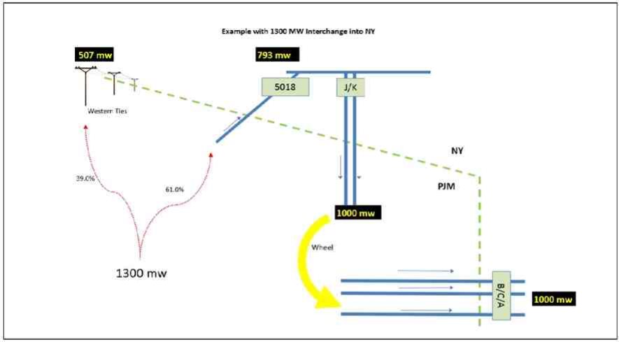
Appendix A - Examples
Figure 1 illustrates an example of how interchange at the Keystone Proxy Bus is handled today, along with the ConEd/PSEG Wheel, in the NYISO Day Ahead and Real-time markets.
Figure 1: Interchange to NY - Today’s View
V 4.0
December 19, 2016
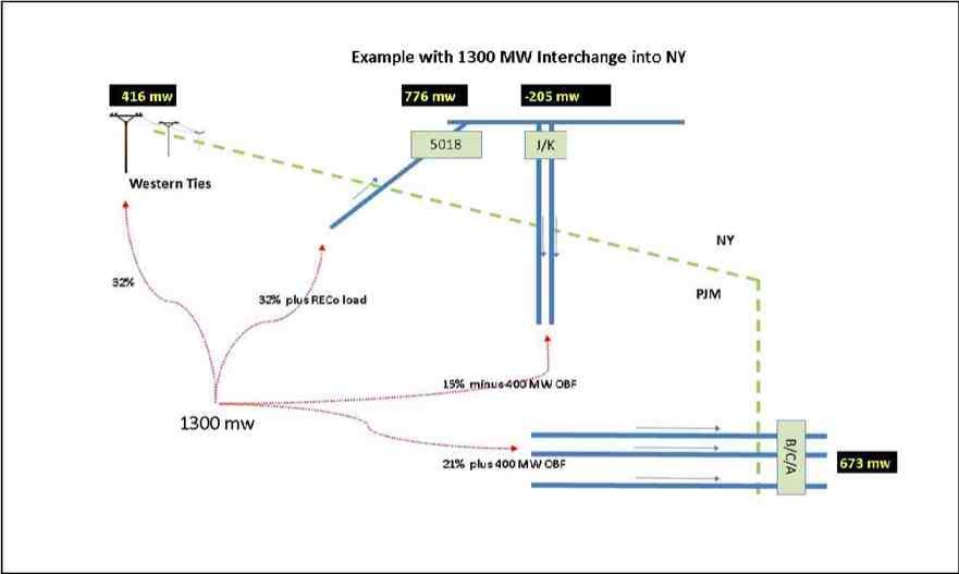
Figure 2 illustrates an example of the NYISO-PJM proposal for handling interchange once the ConEd PSEG Wheel is no longer in place. This example assumes RECo load is 450 MW.
Figure 1: Interchange to NY - Proposed
V 4.0
December 19, 2016
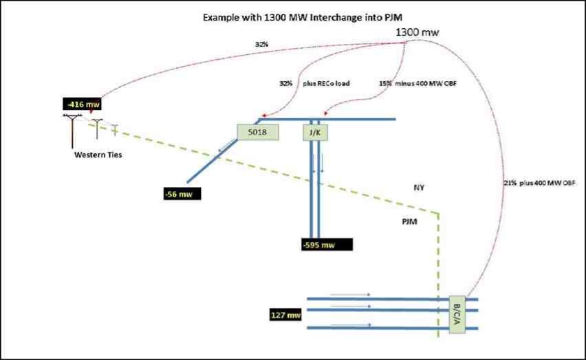
Figure 3 illustrates the same example as in Figure 1, except in the export direction. This example assumes RECo load is 450 MW.
Figure 2: Interchange to PJM - Proposed